Canon imagePASS-B2 Manual de operación y mantenimiento

ENGLISH 日本語
imagePASS-B2 Installation Procedure
imagePASS-B2 設置手順書
This installation procedure is written in Japanese and English. The installation procedure for Japan model is described in Japanese and one for the other modes is
described in English. These procedures are different from each other. Follow the procedure corresponding to the installed model.
- Japanese: The installation procedure for Japan model
- English: The installation procedure for the other models except for Japan model
この設置手順書には、和文と英文の設置手順が記載されている。和文では日本モデル用の設置手順が記載されており、英文では日本モデル以外のその他のモデル用の設
置手順が記載されている。それぞれの設置手順は異なっているので、モデルに応じた手順に従うこと。
・和文: 日本モデル用設置手順
・英文: 日本モデル以外のその他のモデル用設置手順
PRINTED IN USA 45110734 PUB No. FT1-0694-000

2
2
Check Items when Turning OFF the Main Power
Check Items when Turning OFF the Main Power
How to Check this Installation Procedure
When Using the Parts Included in the Package
A symbol is described on the illustration in the case of using the parts included in the package
of this product.
Packaged Item
Symbols in the Illustration
The frequently-performed operations are described with symbols in this procedure.
Connector
Disconnect
Screw
Tighten Remove Connect Secure Free
Harness
Push
Insert Plug in Turn on
Sound CheckCheck Visual Check
Claw
Remove
Checking instruction
F-1-1
F-1-2
Before Connection
The IP addresses for communication between the host
machine and server are set automatically
1) Enter the Service Mode (level 1).
2) COPIER > OPTION > INT-FACE > IMGCONT> "3"
3) Exit the Service Mode
Securing space for installation
Secure a space to install this equipment as shown in the gure below. A space of 200mm or
more is required from the back of this equipment.
200mm or more
Rear
Equipment
Front
Check Items when Turning OFF the Main Power
Check that the main power switch is OFF.
1) Turn OFF the main power switch of the host machine.
2) Be sure that display in the Control Panel and the lamp of the main power supply are turned
off, then disconnect the power plug.
F-1-3

3
3
Installation Outline Drawing
Installation Outline Drawing
Checking the Content
Europe x 2
USA x 1
[1] PS Unit X 1 [2] Mounting Plate X 1 [3] Support Plate X 2
[4] Power Cord [5] Cross Ethernet
Cable 0.5m X1
[6] Shield Ethernet
Cable 3.0m X1
[7] Interface Cable X 1 [8] Open I/F PCB X 1 [9] Screw (TP; M3x6) X 4
[10] Screw with Toothed
Washer
(Binding small; M4x8) X 8
[11] Stepped Screw (M4)
X 4
[12] Wire Saddle X 3
F-1-4
• [4] Power Cord
The connector has a different shape depending on locations.
2 are packaged in the products for EUR/1 is packaged in the products for USA
Use the correct power code to mach the location/area of installation.
Make sure not to leave unused power code at the site.
< CD/GUIDES >
• Media Pack US
Installation Outline Drawing
F-1-5

4
4
Installation Procedure
Installation Procedure
Installation Procedure
■Installing the Open I/F PCB
1) Remove the Left Rear Cover.
• 2 Rubber Caps
• 2 Screws
• 5 Claws
x2
x5
Claws
Rubber Caps
Rubber Caps
2) When the Reader is installed, remove the Reader Communication Cable.
F-1-6
F-1-7
3) Remove the Left Rear Sub Cover.
• 1 Screw
• 1 Hook
Hook
Left Rear
Sub Cover
4) When the FAX is installed, remove the FAX cable.
F-1-8
F-1-9

5
5
Installation Procedure
Installation Procedure
5) Hold the handle to remove Main Controller PCB 2.
• 2 Screws
x2
Grip
6) Remove the Face Cover. (Removed Face Cover is not used.)
• 2 Screws (Removed screws are not used.)
NOTE:
Ask the user to store the Face Cover and Screws, in case it is needed in the future.
x2
F-1-10
F-1-11
7) Remove the 2 screws (the removed screws are used in step 9)).
x2
8) Remove the Bypass PCB (the removed Bypass PCB is not used).
• 2 Screws (the removed screws are not used)
NOTE:
Ask the user to store the Bypass PCB and Screws, in case it is needed in the future.
x2
F-1-12
F-1-13

6
6
Installation Procedure
Installation Procedure
9) Install the Open I/F PCB.
• 1 Connector
• 2 Screws (the screws removed in step 7))
• 4 Screws (TP; M3x6)
x4
x2
10) Install Main Controller PCB 2.
CAUTION :
• Lift the grip and insert the Main Controller PCB 2. When it touches the end, tilt the
grip and install it with 2 screws.
• Make sure to tilt the grip slowly on both sides simultaneously.
• Check that the Main Controller PCB 2 is installed properly.
x2
Grip
F-1-14
F-1-15
11) Install the FAX Cable (if the FAX is installed).
12) Install the Left Rear Sub Cover. (1 Screw)
13) Install the Reader Communication Cable (if the Reader is installed).
14) Connect the Interface Cable to the installed Open I/F PCB.
15) Cut off [A] part of the Left Rear Cover with nippers.
CAUTION:
Be sure to remove adequately so that there is no burr.
[A]
F-1-16
F-1-17
7
7
Installation Procedure > Installing the PS Unit
Installation Procedure > Installing the PS Unit
16) Install the Left Reader Cover. (2 Screws, 2 Rubber Caps)
Installing the PS Unit
1) Remove the 9 Face-Cover Seals on the Rear (The removed Face Seals will not be used.)
2) Install the 2 Support Plates.
• 4 Stepped Screws (M4)
• 4 Screws with Toothed Washers (Binding; M4x8)
Screws with
Toothed Washer
Screws with
Toothed Washer
Stepped Screw
Stepped Screw
x8
F-1-18
F-1-19
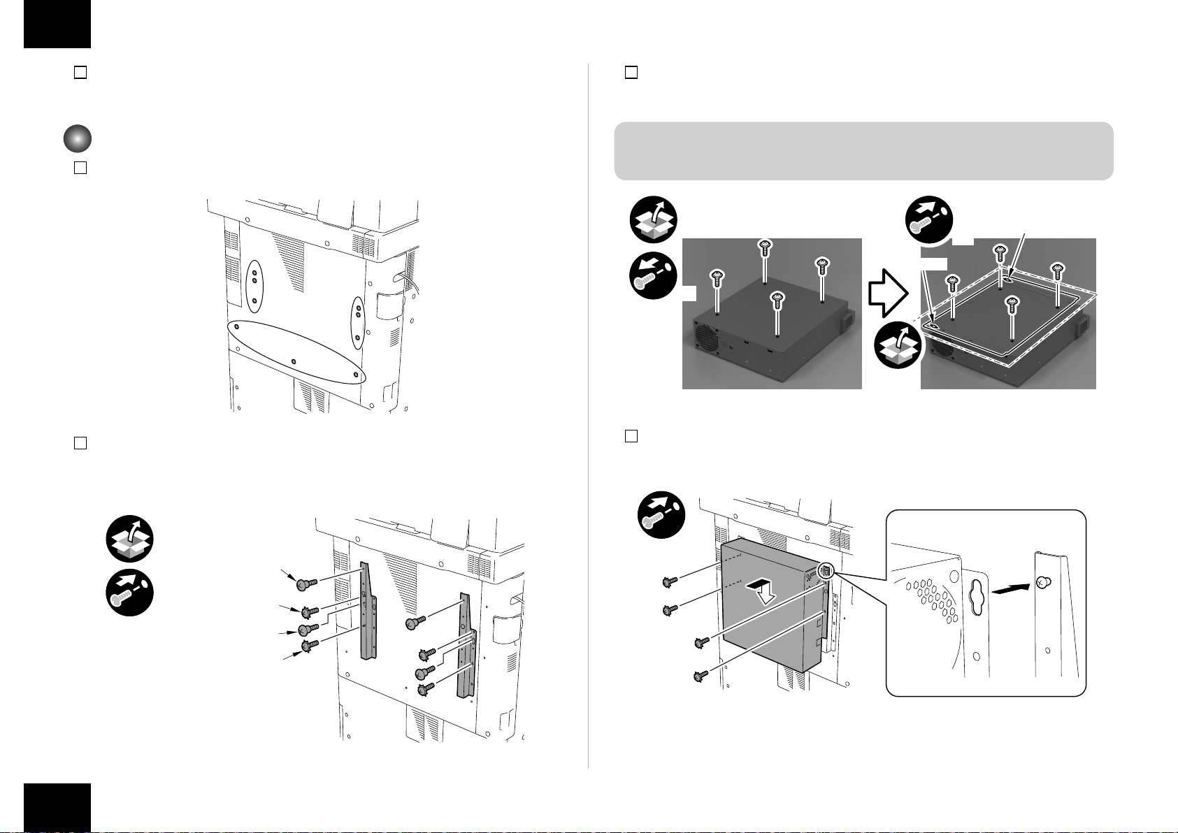
3) Remove the 4 Screws.
4) Install the Mounting Plate with the removed screws.
CAUTION:
Be sure to install it in the correction direction.
x4
x4
Slot Hole
Slot Hole
5) Install the PS Unit in the direction of the arrow.
• 4 Screws with Toothed Washers (Binding: M4x8)
x4
F-1-20
F-1-21

8
8
Installation Procedure > Installing the PS Unit
Installation Procedure > Installing the PS Unit
6) Install the Interface Cable to the PS Unit.
7) Open the Right Rear Cover, connect one end of the Cross Ethernet Cable to the host
machine and then connect another end to the PS Unit.
• 1 Wire Saddle
x2
Cross Ethernet
Cable
Interface
Cable
8) Close Right Rear Cover 1.
F-1-22
9) Install the 3 Wire Saddles.
10) Connect the Power Cord and the Shield Ethernet Cable to the PS Unit.
11) Secure the cables in place using the 3 Wire Saddle as shown in the gure below.
CAUTION:
• Use the correct power code to mach the location/area of installation. Make sure not
to leave unused power code at the site.
• Be sure to use the network cable with Category 5e or higher. In addition, a sealed
type (STP cable) is recommended. When using the non-sealed type (UTP cable), it
may inuence the surrounding electronic equipments via network cable.
x2
x3
Shield Ethernet
Cable Power Cord
F-1-23
F-1-24

9
9
Installation Procedure > Settings after Installation
Installation Procedure > Settings after Installation
12) Turn ON the main power switch of the host machine.
13) "Turn ON the main power of the host machine again." is displayed on the touch panel,
turn OFF the main power switch of the host machine.
14) Turn ON the main power switch of the host machine again.
Settings after Installation
1) At the Main menu, press [Printer].
2) Press [Printer Status/Settings].
F-1-25
F-1-26
3) At the Languages Setup screen, select the name of the language you want to use, and
then select OK.
Wait a few minutes.
<Input of password>
When setting it up, the password input screen is displayed.
Entering "Fiery.1" in the password eld displays the setting screen.
NOTE:
Use single-byte upper case to enter F of "Fiery.1". Use single-byte lower case to enter
other characters.
In response, the machine will automatically show the Settings menu. Be sure to at least select
the following and make the appropriate settings in the indicated order: [Server Setup], [Network
Setup], and [Printer Setup]. For more information, see Conguration and Setup on the User
Documentation.
For instance, once you have made the various settings under [Server Setup], you will be
shown a screen asking you if you want to store the settings. Select [yes] so that the system
will be stored in memory. Unless you have made appropriate settings in the correct order and
saved them, you will not be able to go on to the next item.
F-1-27

10
10
Installation Procedure > Checking the Operation After Making the Settings
Installation Procedure > Checking the Operation After Making the Settings
Making Server Settings:
Make the appropriate settings including the name of the server.
Making Network Settings:
Make the appropriate settings including port, protocol, and service.
F-1-28
F-1-29
Making Printer Settings:
Make the appropriate settings including print queue.
4) Select [close] on the Settings menu. In response, the system will restart automatically.
Checking the Operation After Making the Settings
Print out a test page and a settings page as follows to make sure that all settings have
correctly been made on the equipment and its host machine and that all connections are
normal:
1) At the Main menu, press [Printer].
F-1-30
F-1-31
Tabla de contenidos
Otros manuales de Controladores de Canon

Canon
Canon CR-G100 Manual de usuario

Canon
Canon RC-IP100 Manual de usuario

Canon
Canon Digital Video Software v.32 Manual de funcionamiento

Canon
Canon imageRUNNER ADVANCE C9075S PRO Manual de usuario

Canon
Canon ColorPASS-GX400 Manual de operación y mantenimiento

Canon
Canon imagePRESS C800 Series Manual de funcionamiento

Canon
Canon imagePASS-P2 Manual de usuario


