Cameron 288A Manual de usuario

BARTON NUCLEAR MODEL 288A
DIFFERENTIAL PRESSURE
INDICATING SWITCH
User Manual
Part No. 9A-C10301, Rev. 08
AUGUST 2021
Contents
Safety ............................................................................................................ 2
Section 1—Introduction ................................................................................. 3
General ......................................................................................................... 3
Main Components ......................................................................................... 3
Indicating Switch ...................................................................................... 4
Relays ....................................................................................................... 5
Wiring ........................................................................................................ 5
Diff erential Pressure Unit (DPU) ............................................................... 5
Specifi cations ............................................................................................... 5
Nuclear Qualifi cations ............................................................................... 6
Section 2—Installation ................................................................................... 7
General ......................................................................................................... 7
Mounting/Piping/DPU Installation ................................................................. 7
Electrical Connection (Switches/Relays) ...................................................... 7
Switch Use .................................................................................................... 7
Startup .......................................................................................................... 8
Switch and Relay Wiring Diagrams............................................................... 9
Section 3—Maintenance and Calibration ................................................... 14
Tools............................................................................................................ 14
Bezel/Lens (or Cover) Installation and Removal......................................... 14
Calibration Check........................................................................................ 15
Pointer Installation and Removal ................................................................ 16
Pointer Installation .................................................................................. 16
Pointer Removal ...................................................................................... 16
Indicator Calibration .................................................................................... 17
Drive Arm Tightness Test ......................................................................... 19
Drive Arm Stop Adjustment .................................................................... 20
Switch Calibration ..................................................................................... 20
Calibration Setup ..................................................................................... 20
Calibration Procedure ............................................................................. 21
Changing Switch Set Point ........................................................................ 22
Defi nitions of Terms ................................................................................. 22

2
Safety
WARNING: This symbol identifi es information about practices or circum-
stances that can lead to personal injury or death, property damage, or
economic loss.
CAUTION: Indicates actions or procedures which if not performed correctly
may lead to personal injury or incorrect function of the instrument
or connected equipment.
IMPORTANT: Indicates actions or procedures which may aff ect instrument operation or
may lead to an instrument response that is not planned.
Product Brand
* Mark of Schlumberger.
Other company, product, and service names are the properties of their respective owners.
Copyright © 2017 Schlumberger. All rights reserved.
Best Practices for Set Points ................................................................... 22
Changing Set Point of an In-Service Instrument ..................................... 23
Changing Set Point of an Out-of-Service Instrument .............................. 24
Range Changes ...................................................................................... 24
Parts Replacement...................................................................................25
Troubleshooting ......................................................................................... 26
Section 4—Assembly Drawing and Parts Lists ..................................... 28
Section 5—Dimensional Drawings .......................................................... 34
Appendix A—Model 224 DPU ................................................................A-1
DPU Description ........................................................................................A-1
Specifi cations .........................................................................................A-1
Theory of Operation ...............................................................................A-3
DPU Installation .........................................................................................A-4
General...................................................................................................A-4
Mounting.................................................................................................A-5
Piping .....................................................................................................A-5
Piping Diagrams .....................................................................................A-6
Startup .....................................................................................................A-12
DPU Maintenance ....................................................................................A-12
Required Tools .....................................................................................A-12
DPU Cleaning/Inspection Procedure....................................................A-13
Changing the DPU Range ....................................................................A-14
Replacing the Bellows Unit Assembly (BUA) .......................................A-14
DPU Troubleshooting ...............................................................................A-15
DPU Assembly Drawing and Parts List ....................................................A-17
DPU Dimensional Drawings.....................................................................A-19
3
Model 288A Differential Pressure Indicating Switch Section 1
Section 1—Introduction
General
The Barton* weatherproof Model 288A is a diff erential pressure indicating
switch. The Model 288A has a NEMA-4 watertight die-cast aluminum case
(fi nished with a weather-resistant black epoxy resin paint). The cover lens is
secured in the bezel with an elastomer ring to reduce the possibility of acci-
dental breakage. This ring also acts as a seal between the bezel and the case to
ensure a moisture, fume and dust-free atmosphere for the indicator and switch
mechanism. The large cover lens allows maximum readability of the indicat-
ing pointer.
Switches and all adjustments are readily accessible when the cover is re-
moved.
The built-in switches energize either single or dual alarm circuits when the
measured diff erential pressures exceed predetermined limits. These limits
may be either maximum, minimum, or both.
Main Components
Switch
Arm
Adjust
Switch
Adjust
Adjust
Figure 1.1—Switch components

4
Section 1 Model 288A Differential Pressure Indicating Switch
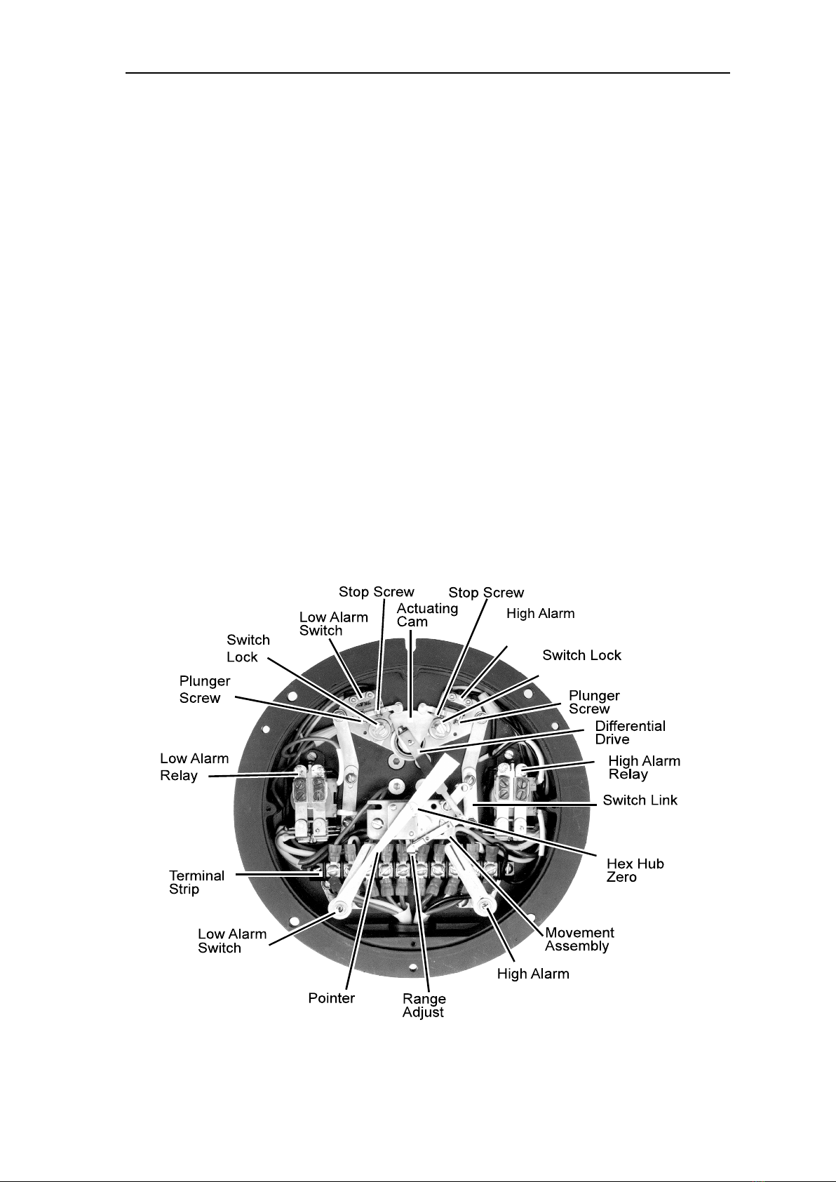
Indicating Switch
(refer to Figure 1.2, Figures 2.1 to 2.6, and Table 2.1)
Rotation of the DPU torque tube shaft is coupled through connecting linkage
within the switch case to move the pointer across the scale plate. An actuat-
ing cam, directly connected to the torque tube shaft, rotates with the motion
of the shaft. Two cam follower roller/actuator arm assemblies, one for each
switch, respond to torque tube rotation by opening and closing the switches as
they ride on and off the cam. The levels of diff erential pressure at which the
switches actuate are adjustable with high and low alarm switch adjustments
on the scale plate.
F igure 1.2—Switch actuation example

5
Model 288A Differential Pressure Indicating Switch Section 1
Standard models can have one or two alarm switches. Each switch can be
connected to operate normally-opened or normally-closed. The direct-set
switch contacts are adjustable over a scale range of 5-95% nominal.
The cam rotates counterclockwise with increased pressure. In Figure 1.2,
page 4, the low switch is set at 25% diff erential pressure, and the high switch
is set at 75% diff erential pressure.
Switches are available in several variations.
• SPDT: This is the standard model (low, high, or both)
• DPDT: Two switches are stacked and actuated by a single lever (low,
high, or both)
• Three or four SPDT: Switches have independent switch points.
Switches 1 and 3 are usually low switches set for decreasing pressures;
switches 2 and 4 are usually high switches set for increasing pressures.
Relays
Relays are actuated by internal switches and are available in several varia-
tions:
• SPDT
• DPDT
• Two SPDT
• Two DPDT
Wiring
No. 22 AWG is used for internal wiring and No. 18 AWG is used for external
wiring.
Diff erential Pressure Unit (DPU)
For detailed information on the Model 224 DPU, see Appendix A.
Specifi cations
General:
Actuating Unit (DPU) ...................... Model 224 DPU
Dial Size ......................................... 6 inches (150 mm)
Temperature Limits (Ambient) ........ -40°F (-40°C) to +180°F (+82°C)
Switch Repeatability ....................... ±0.25% of full scale
Switch Deadband ........................... ±5% (SPDT); ±6% (DPDT)
Switch Type .................................... Mechanical, Snap-Acting; all switches are SPDT
(DPDT switches are stacked SPDT switches with a
common actuator)
Relay Contact Type ........................ Single Pole, Double Throw (SPDT)
Double Pole, Double Throw (DPDT)
Adjustability .................................... 5% to 95% of factory calibrated scale
Activation ........................................ Increasing or decreasing scale

6
Section 1 Model 288A Differential Pressure Indicating Switch
Switch Contact Rating:
5.0 Amps @ 250 VAC, 50/60 Hz1
3.0 Amps @ 30 VDC (Resistive)1,2
1.0 Amp @ 30 VDC (Inductive)1,2,3
1. CSA Approved
2. CE Approved (Voltage limited to less than 50 VDC or 35 VAC for CE applications)
3. Arc suppression recommended for inductive loadings.
Relay Contact Ratings:
10 Amps @ 150/250 VAC
10 Amps @ 14/28 VDC
1.0 HP @ 208/240 VAC
Relay Coil Voltages:
120 VAC @ 5VA Max.
110 VDC @ 2W Max.
Coil Power Requirement:
DC Relay ........................................ 1.5 Watts
AC Relay ........................................ 2.75 Volt Amps
Accuracy of Indications (1 or 2 SPDT Switches):
0 to 30" WC to 0 to 50" WC...............................±1-1/4% of full scale DP
0 to 51" WC to 0 to 60 PSI ................................±1% of full scale DP
0 to 61 PSI to 0 to 150 PSI ...............................±1-1/4% of full scale DP
0 to 151 PSI to 0 to 400 PSI .............................±1-1/2% of full scale DP
0 to 401 PSI to 0 to 600 PSI .............................±2% of full scale DP
0 to 601 PSI to 0 to 1000 PSI ...........................±4-1/2% of full scale DP
1 or 2 DPDT Switches (S401) .......................... Add ±1/2% to above values
Near switch setpoint (±10% full scale) ............. Add ±1/2% to above values
For suppressed ranges .................................... Add ±1/4% to above values
Switch Deadband:
SPDT .............................................. ±5% of full scale DP (max)
DPDT .............................................. ±6% of full scale DP (max)
Accuracy of Repeatability ............... ±0.25% of full scale DP
Nuclear Qualifi cations
The following nuclear qualifi cation applications are based on Cameron Engineering
Report 9A-CR3-288A-13 and 50277306-C-0000193 with switch chatter sensitivity ad-
dressed in Cameron Engineering Report 9A-CR3-288A-19:
• One or two SPDT switches: Radiation Augmented (3 MRads), Full Functional, 12G,
Mild Environment Applications
• One or two DPDT switches: Structural and Pressure Boundary Integrity Applica-
tions
• One or two relays: Structural and Pressure Boundary Integrity Applications
• Three or four independently adjustable SPDT switches: Structural and Pressure
Boundary Integrity Applications

7
Model 288A Differential Pressure Indicating Switch Section 2
Section 2—Installation
General
The instrument should be inspected at time of unpacking to detect any dam-
age that may have occurred during shipment.
IMPORTANT: The DPU was checked for accuracy at the factory. Do not change any of
the settings during examination or accuracy could be aff ected.
For applications requiring special cleaning/precautions, a polyethylene bag
is used to protect the instrument from contamination. This bag should be
removed only under conditions of extreme cleanliness.
Mounting/Piping/DPU Installation
Dimensional drawings are provided in Section 5, page 34. See Appendix A for
Model 224 DPU installation and maintenance information.
Electrical Connection (Switches/Relays)
Units are supplied with either single or dual alarm switches and/or relays
(depending on customer order). The direct-set switch contacts are adjustable
over 5% to 95% of the scale range.
Table 2.1, page 8, shows switch and relay wiring color coding for legacy and
current confi gurations. Figures 2.1 through 2.6 show switch and relay wiring.
The high switch and low switch set point adjustment procedures are covered
in Changing Switch Set Point, page 22.
For physical location of switches, see Figure 1.1, page 3.
Switch Use
Switch contact life and setpoint repeatability are infl uenced by various ap-
plication conditions such as temperature, humidity, airborne contamination,
vibration, amount of plunger travel, cycling rate, and rate of plunger travel
(and others), as well as by the electrical (circuit) characteristics.
IMPORTANT: Field calibrations and switch setpoint testing should be performed at
the same application conditions as expected when the instruments are
required to perform their safety functions. Performance testing at one ap-
plication condition may not necessarily ensure appropriate performance
at another condition.

8
Section 2 Model 288A Differential Pressure Indicating Switch
IMPORTANT: Arc suppression for inductive loads will prolong the life of the switch
contacts.
IMPORTANT: Due to their size, subminiature switches have small mechanical clear-
ances; therefore, no rating above 250 VAC has been established.
Table 2.1—Switch/Relay Wire Color Coding (4/06c)
288A LEGACY CONFIGURATIONS
(prior to Apr. 2006) 288A CURRENT CONFIGURATIONS
NO C NC NO C NC
SPDT SWITCHES
Low Red Yellow Blue Red Yellow Blue
High Black Green White Black Violet Orange
DPDT SWITCHES
Low #1 Red Yellow Blue Red Yellow Blue
Low #2 White/Red White/Yellow White/Blue White/Red White/Yellow White/Blue
High #1 Black Green White Black Violet Orange
High #2 White/Black White/Green White/Violet White/Black White/Violet White/Orange
4-INDEPENDENTLY ADJUSTABLE SWITCHES
Low #1 Red Yellow Blue Red Yellow Blue
Low #2 White/Red White/Yellow White/Blue White/Red White/Yellow White/Blue
High #1 Black Green White Black Violet Orange
High #2 White/Black White/Green White/Violet White/Black White/Violet White/Orange
SWITCHES FOR RELAYS
Low Red Yellow Blue (Note 1) White/Brown Brown White (Note 1)
High Black Green White (Note 1) White/Gray Gray White (Note 1)
RELAYS
Low #1 Gray Blue Brown Red Yellow Blue
Low #2 White/Gray White/Blue White/Brown White/Red White/Yellow White/Blue
High #1 Violet White Orange Black Violet Orange
High #2 White/Violet White/Black White/Orange White/Black White/Violet White/Orange
Coil
Wiring:
Legacy Ver.: Low = Red and High = Black Current Ver.: Low = White/Brown and High = White/
Gray
Note 1: Wire is NOT connected.
Startup
For startup procedures, warnings, and other information, refer to Appendix A .
IMPORTANT: To ensure the unit calibration is within factory-set calibration tolerances,
perform the Calibration Check procedure on page 15.

9
Model 288A Differential Pressure Indicating Switch Section 2
Switch and Relay Wiring Diagrams
IMPORTANT: Figures 2.1 through 2.6 show: switch & relay contacts in the relaxed
(shelf) condition, the low switch set to trip at a position below the pointer
scale position, and the high switch set to trip at a position above the
pointer scale position. NO = Normally Open in (shelf) condition. NC =
Normally Closed in (shelf) condition. C= Common.
Figure 2.1—Low/high SPDT switch diagrams
(current confi guration color codes - see Table 2.1, page 8)

10
Section 2 Model 288A Differential Pressure Indicating Switch
Figure 2.2—Low/high DPDT switch diagrams
(current confi guration color codes - see Table 2.1, page 8)
Tabla de contenidos
Otros manuales de Cambiar de Cameron


