Burke TRI-FLEX II Guía de inicio rápido

TRI-FLEX II BED - OPERATION MANUAL 1
Introduction page 2
-DeviceOverview page 2
-TypographicalOverview page 3
-Symbolsand Warnings page 3
Specifications page 4
IdentificationofMajor Components page 5
ControlSchematic page 6
PendantControlInformation page 6
(optional)Scalesystemschematic page 7
ImportantSafetyInformation page 8
Setup/ Disassembly Instructions page 9
-UnfoldingForUse page 9
-FoldingforTransport page 11
BasicOperationalInstructions page 12
-FunctionDescription page 12
-IVPoles page 12
-Siderailwidthadjustment page 12
- CPR Procedure page 14
-PatientRestraint page 14
-PatientTransfers page 14
-Transportingthe Bed & Patient page 15
CleaningInstructions page 16
Storage of the Bed page 16
Service/Fuses page 16
Troubleshooting page 17
Copyright2003Burke, Inc.
Allrightsreserved.Nopartofthis text shall be reproduced or transmitted in
anyformormeans, electronic or mechanical, including photocopying,record-
ing,orby any information retrieval system withoutwrittenpermissionof
BURKE,INC.
Tri-FlexII is atrademarkofBurke,Inc.
Theinformationin this manualissubjecttochange without notice. Burke,Inc.
makesnocommitmenttoupdateorkeepcurrent,theinformationcontained
inthis manual.
Additionalcopiesof this manual may be obtainedfromBurke, Inc. Please
contactyour local representative.
Table of Contents

2 TRI-FLEX II BED - OPERATION MANUAL
TRI-FLEX II BED
OPERATIONALMANUAL
Overview
Thisbedisintendedfor use whenever a patient’s weight and/
oroverallsizeexceedsexisting unit limitations or patient’s
weightexceedsthatwhich the staff can care forwithoutreduc-
ingthequalityofserviceandendangeringthesafetyofpatient
andstaff. This patient weightusuallyincludesanyoneover 400
lbs(181.4 Kg) but not to exceed 1000 lbs (454.5 Kg).
TheTri-FlexIIbedismulti-purposecapable.Thepatientsur-
face can be raised or lowered to facilitate patient care. The
bedhastrendelenberg and reverse trendelenberg function in
thependantas well as “Cardio-Chair” positioning.
TheTri-FlexIIsystemcan also facilitatepatienttransport.The
twofootendcasterscontainsteering lock ability which pro-
videsdirectionalcontrol during transport.
NOTE: Thismanualcoversthe use and functions of the basic
bed. Instructionsforvariousoptionsandaccessoriessuchas
scalesystemsandmattresssystemswillbecovered in supple-
mentalliteratureprovidedwiththoseaccessories.
Operating Precautions
Beforeoperatingthisbedinsurethatyouhavereadandunder-
stoodindetailthe content of this manual. Itisimportantthatyou
readandstrictlyadheretothesafetyinformationcontainedin
thismanual.Thisproductisintended for indoor use at room
temperatureswithintermittent operation consistentwiththe
stateddutycycleof the device.
Any reference to a side of the bed is from the patient’s view
layinginthebed on their back.
Introduction

TRI-FLEX II BED - OPERATION MANUAL 3
Typographical Conventions
Thismanualcontainsdifferenttypefacesand icons designed to improve readability and increase
understandingof content. Notethefollowingexamples:
•Standardtext - usedforregularinformation
•Boldface text - emphasizes a word or phrase.
•NOTE:-in boldface type and capitalletters, this sets apart specialinformationor important
instructionclarification.
Symbols and Warnings
•Thesymbol belowhighlightsa WARNINGorCAUTION:
-AWARNING identifies situations or actions that may affectpatient or user safety. Disregard-
ingawarning could result in patientoruser injury.
-ACAUTION pointsout special procedures or precautions that personnel must followtoavoid
equipmentdamage.
•Thesymbolbelow indicates READ MANUAL. This symboloccurs on bed labels that indicatea
functionorprocedurethatmaybebetterdefinedinthemanualshouldsomequestionarisere-
gardingoperation.
• The symbol below indicates that this product is identified as a Class B device:
•Thesymbolfollowingindicatesthatthisdeviceis for indoor use only:
•Thesymbolbelowindicatesabattery:
Introduction

4 TRI-FLEX II BED - OPERATION MANUAL
Mechanical
TotalPhysical Length,EndtoEnd: 94”
TotalPhysicalWidth: 40.75”
TotalPhysical Weight: 575-lbs(w/o scale)
TotalShipping Weight: 650-lbs
PatientSurfaceLength: 86”
PatientSurfaceWidth: 48”
PatientSurfaceTransportWidth: 37”
DeckHigh: 28”
Deck Low: 14”
Maximumangleof head gatch elevation: 60 degrees
Maximumangleof upper foot gatch elevation: 24 degrees
Maximumangleoflowerfoot gatch decline: 26 degrees
Maximumangle of trendelenberg 12 degrees
Electrical
Inputvoltage: 120VAC, 60Hz
Current: 2.7 amperes
Outputvoltage: 28V DC
Classification: Class B 1P-54
DutyCycle: intermittentoperation/10%,6-min/hr.
(2)Fusesincontrolbox 5x20mm1.6L250VTime-Lagfuse
(1.6A/250V)
WickmannSeries19195 or equivalent
Scale (optional)
Accuracy: Overall=1%
Weight Capacity: 1000-lbs/ 454.5-Kg
PowerRequirement: 6x C-sizeAlkaline
Readingsperbatteryset 8000(approx)
Options and Accessories
InBedScaleSystem
Trapeze
Dual Passage Assist
ManufacturedbyBurke,Inc.
1800 Merriam Lane
KansasCity, Kansas
Specifications
TRI-FLEX II BED - OPERATION MANUAL 5
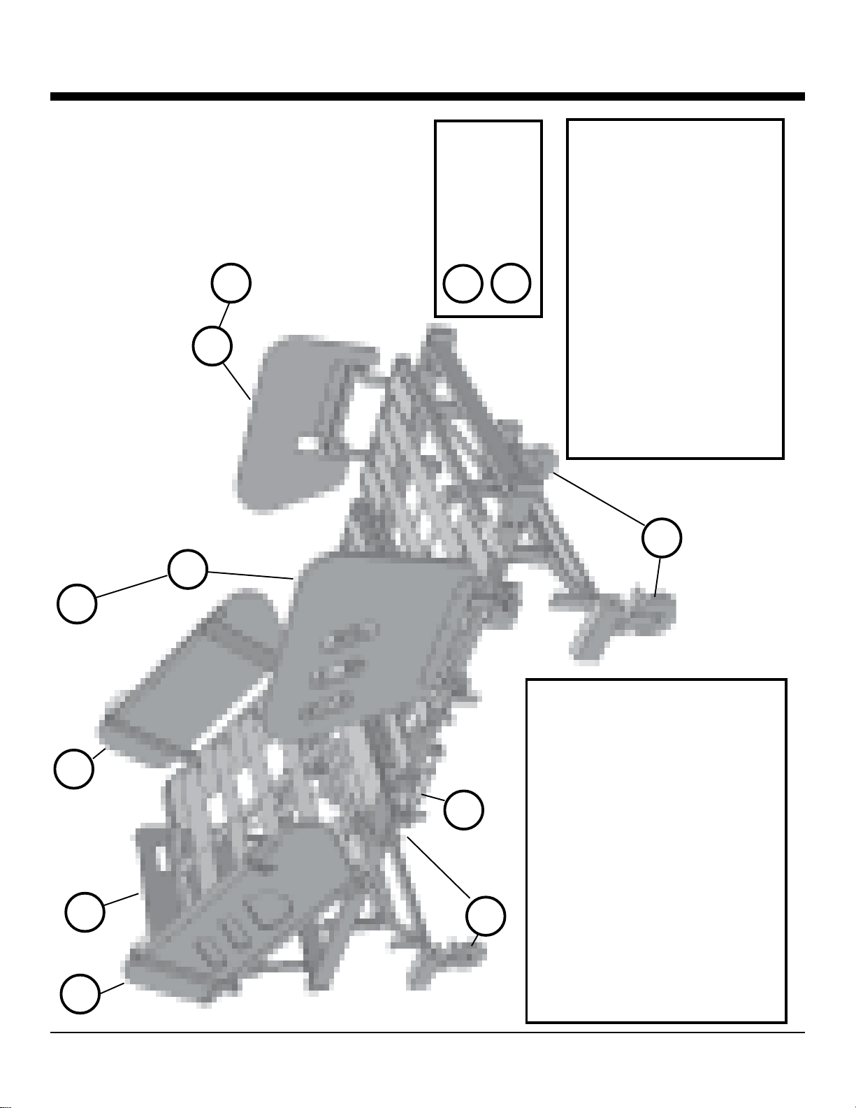
Major Component Identification
Itemsshownwithasterisk(**)arelocated
underbedand not easily showninillustration
** 62000 CONTROL BOX
** 62327 PENDANT
** 62002 BACKUP BATTERY
** 63082 HEADACTUATOR
** 62004 KNEEACTUATOR
** 62005 H/LHEADACTUATOR
** 62006 H/LFOOTACTUATOR
** 62236 A/C POWER CORD
1 63053 TURNBUCKLE
2 63118 HEAD BOARD ASSY
3 63119 FOOT BOARDASSY
4 63081 LOCKING CASTER
5 63080 STEERING CASTER
6 63105 RH HEAD PULLOUTASSY
7 63106 LH HEAD PULLOUTASSY
8 63107 RH FOOT PULLOUTASSY
9 63108 LH FOOT PULLOUTASSY
10 63234 RH FOOT FOLD DOWNASSY
11 63233 LH FOOT FOLD DOWNASSY
12 63097 TRANSPORT POLEASSY
1
2
6
3
5
4
7
10 11
9
12
8
(notshownin
thisillus-
removedfor
clarity)
(LHnotshown
inthisillus-to
showboth
stylesinplace)
(RHnotshown
inthisillus-to
showboth
stylesinplace)

6 TRI-FLEX II BED - OPERATION MANUAL
Thecontrolboxforthe bed is located under the headgatchontheleft side of
thebed.Thisschematic is also on a label located onthecontrol box. The
abbreviationsareasfollows:
H =Headgatchactuator
K =Kneegatchactuator
H/L-H = Hi/oHeadactuator
H/L-F = Hi/LoFootactuator
BB =BatteryBackup
P =Pendant
ACIN =AC power cord
Electrical Schematic
Pendant Controls Thependantcontrolof the bed controlsallbedfunctions.The
pendantsymbolsaredefinedasfollows:
HEADGATCH - UP/DOWN
adjustsupperbodyforpatientcomfort
KNEEGATCH - UP/DOWN
adjustkneeforpatientcomfort
FULLBEDHI/LOW-UP/DOWN
adjustsbedheightfortransferand/orotherpatientcare.
returnto fulldownwhenpatient isunattended
TRENDELENBERG-UP/DOWN
adjustfull bedfortrendelenbergfunction
HEAD/KNEE - UP/DOWN
bothheadand knee gatchworksimultaneously
Control Schematics

TRI-FLEX II BED - OPERATION MANUAL 7
Scale System Wiring Diagram (Optional)
TRI-FLEXIISCALESYSTEMWIRING DIAGRAM

8 TRI-FLEX II BED - OPERATION MANUAL
WARNING: Allpersonswith access to the bedmust read the entire manual beforeusing the bed. Fail-
uretodoso could result in improper usewhichcould damage the bed or injurepersons.
WARNING: 1,000lb.patientuse WEIGHT LIMIT. Use of bed withpersonsabove this weight may
cause damage to bed and persons.
WARNING: To transport a patient in bed, the bed high-low
must be in its’ lowest position with the frame resting on the
transverse caster bars (see figure 1). Failure to do so could
resultincompromising the structural integrity andstability of
thebed which could damage thebed or injure persons. See
transportsection of themanual.
WARNING: Possiblefire hazard exists when bed is used
withOXYGEN administeringequipmentotherthananasalmask or 1/2bedlengthtent. Oxygententsshould
notextendbelowthemattresssupportlevel.
WARNING: AVOID CONTRACT WITH INJURED SKIN. It is not intended for this device to come in
contactwithinjuredskin. Ensure that injured skin is properly protected.
WARNING: TheTri-FlexII electronics are not designed to be used in environmentscontainingFLAM-
MABLE ANESTHETICS. Possible fire hazard exists.
WARNING: Keep the SIDERAILS in a raised position while patient is on the bed to prevent patient from
accidentallyfallingoff the bed.
WARNING: Bed should be leftinthelowestposition when unattended in order to reduce the risk of injury
duetofallswhilegettingintoor out of the bed, or while lying on the bed..
WARNING: If PATIENT RESTRAINTS areused,theymustbeattachedtosomepointonthebed that
articulateswhenthegatchesareraisedand lowered.Failuretodosocouldresultin therestraintsinjuring
thepatient.
WARNING: TomaximizethefullscopeofUL-60601,thisbedisintendedforpatientuseinONLYtheMAXI-
MUMWIDTHCONFIGURATION.Withinthecurrentstandard,patientandcaregiversaresafelyremovedfrom
pinchpointsandmovingcomponentswhichcouldcauseharm.Configurationsotherthandescribedreduce
thedistancetothesepointswhichcouldresultinseverepersonalinjuryorequipmentdamage.
CAUTION: Run the POWER CORD under the bed frame and positioned so as to prevent being walked
onorrolled over by the bedcastersor interfering with moving partsof the bed. Keep thepowercord
pluggedintoa wall outlet.
CAUTION: Hangthehand CONTROL PENDANT on the side railwhen not in use. Run the cordunder
the bed frame and keep it clear of moving parts to prevent possible damage to the cord.
CAUTION: When the bed is in use, the CASTERS must be positioned so that the locking tabs are
locked, and pointed towards the foot end of the bed. Failure to do so will cause damage to the bed.
CAUTION: Keepthehead of the bed a minimumof4" from walls to avoid contactingawall when running
thehi-low. Failureto do so could result indamagetothe bed and/or the wall.
•Elevatingtheheadgatchfacilitateseasier breathing for heavierpatients.Consult a doctor.
•Ifneeded,orthopedicequipmentcan be attached to the bed.
Figure 1
Important Safety Information

TRI-FLEX II BED - OPERATION MANUAL 9
NOTE: MOVE BEDTOAN OPENAREALARGE ENOUGH TO UNFOLDTHE BED. IF YOUR BED IS
NOTEQUIPPEDWITHTHE OPTIONALSCALESYSTEM,PLEASEDISREGARDTHEINFORMATION
PERTAININGTOTHE SCALE SYSTEM.
UNFOLDING THE BED FOR USE
1. Set the head and foot boards aside to be assembled
later.Alsoremove the twoturnbucklesandsetasideforlater
use.
2.WARNING: Lockthe four transport casters to prevent the
bedfrommovingwhen you unfold the head and foot sections
asmovementcould cause injury.Thelockedcastersshould
befacingoutwardandbeperpendicularto the centerline of
the bed for storage (see figure 8).
3.Remove
the“L”
shapedfoot
endtrans-
portlatch
locatedon
thetrans-
portpole.
(seefigure
9)
4.Gentlylowerthefootendsectionofthebed.
WARNING:Ifthe foot end or headendof the bed is allowedtodrop while being lowered, injuryto
personsand/ordamage to the bed couldoccur. (see figure 10)
5.Makesurethattheblackwovensafety strap located at the head
endofthebed is securing the head gatchpatientsupport surface
to the base (see figure 11) .
WARNING: Unexpectedmovementofthepatientsupportsurface
andpossibleinjurycouldoccurif the safety strap is not in place.
CAUTION:Loosen this safety strap before operatingthe bed.
6.Removetheheadendtransport latch bracket located on the
transportpoleplacedverticallyinthecenterofthebed.
7.Gentlylowertheheadendsectionofthebed.
Figure 8
Assembly/ Disassembly Instruction
Figure 9 Figure 10
Figure 11

10 TRI-FLEX II BED - OPERATION MANUAL
WARNING:Ifthefootendorheadendofthebedisallowedtodropwhilebeinglowered,injurytopersons
and/ordamagetothebedcouldoccur (see figure12).
8.Releasetheblackwovensafety strap located at the head end of the
bedandremove theTool(see figure 14).
9.Pintheturnbuckleinplaceattheconnectionpointsbelowthehead
andfoot sections of the bed. (DOONE SIDEATATIME)Using the
Tool providedplaceoneend throughthecenterof the turnbuckle.
Look forthedots on the end of the screwsandreference them to the
marksontheturnbucklebody. (seefigure13). Asyouadjustthe
turnbucklebodythedots on the screws will move toward eachother
whentightening and awayfromeachotherwhen loosening.Observe
thecorrect
movement
inwardasyouinstallthispiece.Observethe
correctmovement outwardwhenremovingthis
piece.
WARNING: Installand completelytightenone
turnbuckleand theninstallandtightentheother
side.Failuretoproperlyinstall the turnbuckles
couldresultininjury to persons and/or damage
tothebed.
10.StoretheTool inVelcroholderwith black safety
strap as in figure 14).
11. CAUTION: Position and lock the four casters
(locatedatthecornersoffthebed) with locking
tabsfacingthe
footend ofbed. Failuretodo sowillresultindamage tothe
castersduringhi-low use.
12.Plugbedpowersupply into anACoutlet.
13.Raisebed hi-low approx. 5 inchesto take weight off ofthe center
transportwheels.
14.Removethepull pin securing the central transportsystem. Pivot
theaxleinwardandup. Aligntheholestowherethecasters are
tuckedupunderthebedandreplacethepullpin.
15.Raisethehead gatch and store the central transport poleinit’s holder under the head gatch (see
figure15)
16.LowertheHi-low system.
Assembly/ Disassembly Instruction
Figure 12
Figure 13
Figure 14
Otros manuales para TRI-FLEX II
2
Tabla de contenidos
Otros manuales de Equipo médico de Burke


