Broadcast Tools Status Sentinel Manual de usuario

Installation and Operation Manual
Due to the dynamic nature of product design, the information contained in this
document is subject to change without notice. Broadcast Tools, Inc., assumes no
responsibility for errors and/or omissions contained in this document. Revisions
of this information or new editions may be issued to incorporate such changes.
Broadcast Tools® is a registered trademark of Broadcast Tools, Inc.
tiny TOOLS™ is a trademark of Broadcast Tools, Inc.
All Sentinel™ labeled products are a trademark of Broadcast Tools, Inc.
Copyright ® 1989 - 2009 by Broadcast Tools, Inc. All rights reserved.
No part of this document may be reproduced or distributed without permission.
Visit www.broadcasttools.com for important product update information.
Manual Update: 04/15/2009
Status Sentinel
INC
®

e-mail:
voice:
360.854.9559
fax:
866.783.1742
Status Sentinel Installation and Operation Manual
Table of Contents
Section Title Page #
Introduction..............................................................................................................3
Safety Information ...................................................................................................3
Who to Contact for Help .........................................................................................3
Product Overview ....................................................................................................4
Inspection.................................................................................................................4
Installation ..............................................................................................................4
Surge Protection ................................................................................................4
UPS Standby Power System .............................................................................4
“NET” Network connector ...............................................................................4
POWER connector ............................................................................................4
Status/Digital input connection..........................................................................5
Power and Status LED’s....................................................................................5
On-board 5VDC power source ..........................................................................5
Chassis ground ..................................................................................................5
Web Setup/Operation ...............................................................................................5
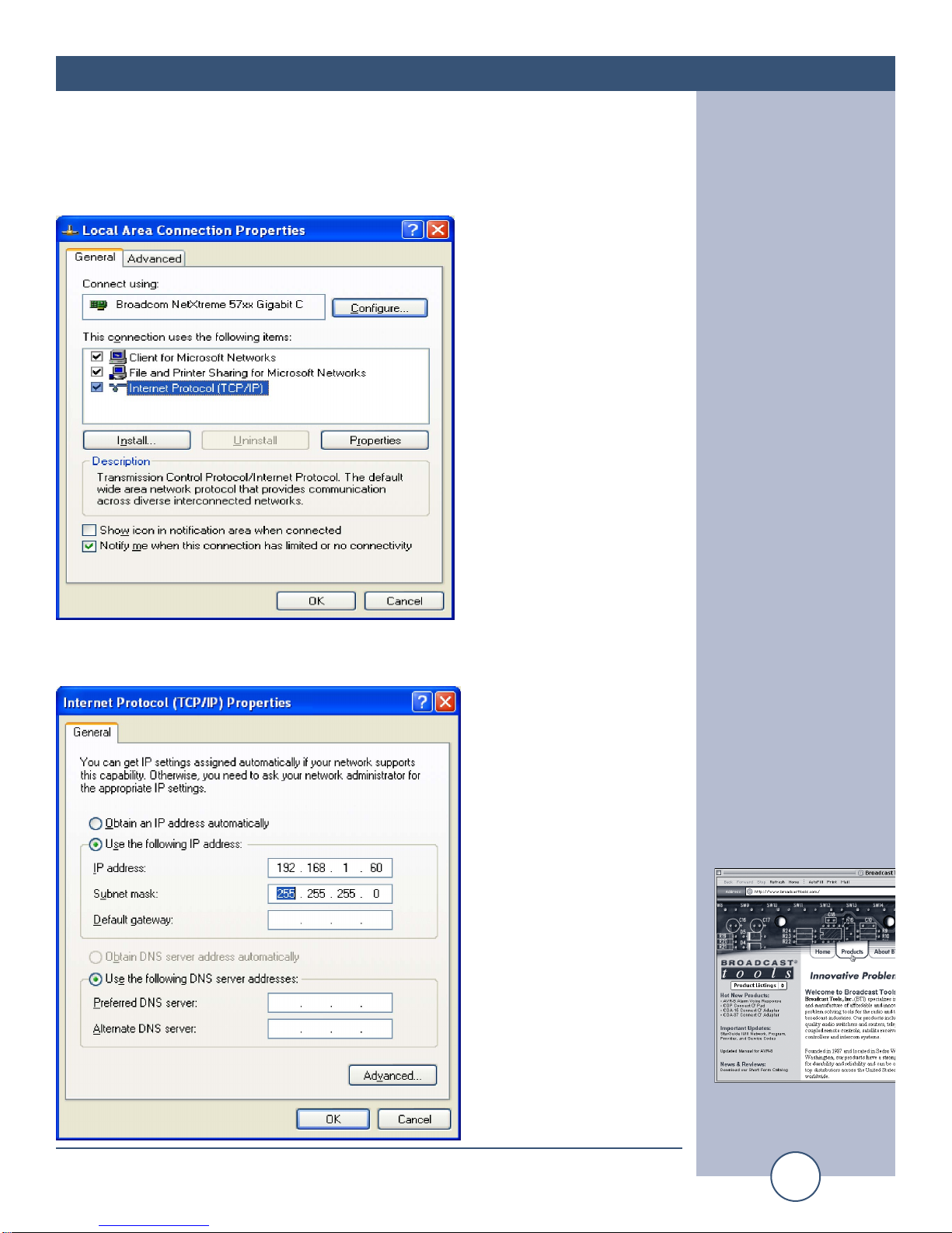
Ethernet “Quick Start” guide.............................................................................5
Opening the LOGIN Web Page .........................................................................8
“Login” Web Page ............................................................................................9
“Monitor/Control” Web Page ..........................................................................10
“User Setup” Web Page ..................................................................................11
“Status Setup” Web Page.................................................................................12
“Email/Network Setup” Web Page ..................................................................13
Restoring Network Factory Defaults...............................................................13
“Show Log” Web Page ...................................................................................15
“About” Web Page...........................................................................................16
Specifications.........................................................................................................17
Warranty.................................................................................................................18
Declaration of Conformity.....................................................................................19
WEBSITE:
Visit our web site for
product updates and
additional information.
2
CONTENTS

e-mail:
voice:
360.854.9559
fax:
866.783.1742
3
Status Sentinel Installation and Operation Manual
INTRODUCTION
INTRODUCTION
Thank you for your purchase of a Broadcast Tools® Status Sentinel™ Web
enabled three-input status/digital module (referred to as the Status Sentinel™
throughout this manual). We’re confident that this product will give you many
years of dependable service. This manual is intended to give you all the infor-
mation needed to install and operate the Broadcast Tools® Status Sentinel™.
SAFETY INFORMATION
Only qualified personnel should install Broadcast Tools® products. Incorrect or
inappropriate use and/or installation could result in a hazardous condition.
Broadcast Tools, Inc., is unable to support NON-Broadcast Tools software, hardware or
NON-Broadcast Tools computer/hardware/software problems. If you experience these
problems, please research your hardware/software instruction manuals or contact the man-
ufacturers technical support department.
WHO TO CONTACT FOR HELP
If you have any questions regarding your product or you need assistance, please con-
tact your distributor from whom you purchased this equipment.
If you would like more information about Broadcast Tools® products, you may
reach us at:
Broadcast Tools, Inc.
131 State Street
Sedro-Woolley, WA 98284-1540 USA
Voice: 360.854.9559
Fax: 866.783.1742
Internet Home Page: www.broadcasttools.com
E-mail: [email protected]
THANK YOU FOR CHOOSING
BROADCAST TOOLS® BRAND PRODUCTS!
CAUTION!
Broadcast Tools®
Products, as with any
electronic device, can
fail without warning.
Do not use this product
in applications where a
life threatening condition
could result due to failure.
NOTE:
This manual should be
read thoroughly before
installation and operation.
WEBSITE:
Visit our web site for
product updates and
additional information.

e-mail:
voice:
360.854.9559
fax:
866.783.1742
4
Status Sentinel Installation and Operation Manual
OVERVIEW
Product Overview
The Status Sentinel™ is a robust, full-featured; Ethernet based data acquisition
device with three optically isolated status (digital) inputs. The Status Sentinel™ can
be controlled and/or monitored over any IP network including private networks, IP-
based industrial control networks, and the Internet. Users can operate the product
using a web browser or web-enabled mobile device, while email notification may be
configured to alert up to four recipients when alarms are detected. The user may
also enable a sound effect to play when an alarm is generated. Logging of input sta-
tus, along with the site ID text may be emailed from once an hour to once a day.
The Status Sentinel™ may be paired with the Relay Sentinel™ to form a “Relay
Extension Cord”.
Inspection
Please examine your Status Sentinel™ carefully for any damage that may have been
sustained during shipping. If any damage is noted, please notify the shipper imme-
diately and retain the packaging for inspection by the shipper. The package should
contain the Status Sentinel™, this manual and/or CD, 7 foot BLUE straight-through
CAT 5 cable, 7 foot GRAY crossover CAT 5 cable, and the 7.5 VDC @ 500ma wall
transformer.
Installation
Surge Protection
The Status Sentinel™ has built-in resistance to voltage changes; we recommend that
you use a power surge protector or line conditioner on the incoming AC line.
Lightning strikes and/or other high voltage surges may damage your Status
Sentinel™ and connected equipment if it is not properly protected. For lightning
protection devices, check out www.polyphaser.com and www.itwlinx.com.
UPS Standby Power System
We recommend that you connect your Status Sentinel™ to a UPS system. A UPS
helps minimize the risk to the Status Sentinel™ and provides power during a power
outage.
“NET” network RJ45 connector
Connect one end of the supplied CAT5 (straight or crossover) cable to the desired
ETHERNET (WAN/LAN) or PC port.
POWER 7.5 VDC connector
This is the connector used to power the unit. Never use any type of power supply
other than the specified power supply.
CAUTION!
Installation of the Relay
Sentinel™ in high RF
environments should be
performed with care.
The station ground
should be connected to
the designated chassis
ground terminal or
chassis ground screw
using a 20 to 24-gauge
wire.

e-mail:
voice:
360.854.9559
fax:
866.783.1742
5
Status Sentinel Installation and Operation Manual
INSTALLATION
Installation
Status/Digital (OPTO +/-) 1,2,3 input connections
The optically isolated status/digital inputs accept (WET) voltages from 5 to 24 volts
DC. Higher voltages may be applied if an appropriate value external current limit-
ing resistor is used. Connect the positive voltage to the desired “OPTO +” terminal
(anode) and ground or minus voltage to the desired “OPTO –“ terminal (cathode).
NOTE: Please observe proper polarity.
Connecting (DRY) contact closures to the status/digital input requires the user to
connect the 5VDC terminal to the desired OPTO + terminal. Connect one side of
the external contact closure to the GND terminal and the other side of the external
contact closure to the desired OPTO – terminal.
NOTE: Please observe proper polarity. The on-board 5VDC power source may be
used to power the (DRY) inputs.
Power LED
Indicates power is applied.
OPTO-Input 1,2,3 LED’s
Illuminates when the appropriate status/digital input is activated.
On-board 5VDC power source
The on-board five-volt DC power source may be used to power the status/digital
input and/or external equipment. The supply is current limited to 100ma.
Connections should be made to the “5VDC” and “GND” terminals.
CHS GND connector
Connect the station ground to this terminal.
Web Setup/Operation
Ethernet “Quick Start” guide
M CAUTION! If you are not familiar with Ethernet enabled equipment, it may be
useful to contact your IT department, network administrator or network consultant
for help. Assigning an IP address already in use by another device may cause prob-
lems with your network! Instructions for changing the IP address of the computer
that will be used for the configuration of this product are given here. Note that these
instructions are specifically for computers with the Windows XP operating system.
For setup using other operating systems, refer to the appropriate OS users manual.
CAUTION!
NEVER DOWNLOAD
FIRMWARE UPDATES
OR CHANGES TO
THE XPORT WEB-
SERVER UNLESS
INSTRUCTED TO DO
SO BY BROADCAST
TOOLS®. DOING SO
DELETES ALL SOFT-
WARE AND VOIDS
ALL WARRANTIES
FROM BROADCAST
TOOLS, INC.
WEBSITE:
Visit our web site for
product updates and
additional information.

e-mail:
voice:
360.854.9559
fax:
866.783.1742
6
Status Sentinel Installation and Operation Manual
SETUP
Web Setup/Operation
Step 1: Open the control panel by clicking on the start menu, click on settings, then
click on Control Panel. (Note that the control panel shown is in “Classic View”. If con-
trol panel is in “Category View” select the “Classic View” option before proceeding.)
Step 2: Double click on the icon labeled Network Connections. The following
menu will pop up.

e-mail:
voice:
360.854.9559
fax:
866.783.1742
7
Status Sentinel Installation and Operation Manual
SETUP
Step 3: Right click on the icon labeled Local Area Connection. Another menu will
appear. Select the option at the bottom of the menu labeled Properties. The Local
Area Connection Properties window will appear.
Step 4: On the Local Area Connection Properties page, double click on Internet
Protocol (TCP/IP) to display properties.
WEBSITE:
Visit our web site for
product updates and
additional information.

e-mail:
voice:
360.854.9559
fax:
866.783.1742
8
Status Sentinel Installation and Operation Manual
SETUP
Step 5: Before making any changes to the network settings, write down the current
settings (or screen capture the page and print) so that they can be restored once the
unit is configured. Next, select the radio button labeled “Use the following IP
address” and type in the IP address 192.168.1.60. Type in the subnet mask of
255.255.255.0. Leave the default gateway field blank. Click OK to apply the new
settings.
Opening the LOGIN Web Page
1. Connect the supplied GRAY colored XOVER cable between the PC’s Ethernet
port and the products NETWORK RJ45’s jack.
2. Connect the supplied 7.5 VDC power supply to the product’s power jack labeled
Power 7.5 VDC. Verify that the green POWER LED and left “LINK” LED
above the “NET” Network RJ-45 are illuminated
Ethernet (NETWORK) port LED indicator functions
3. Open the product’s login page by typing the following URL into the browser:
http://192.168.1.55 A username and password is required to change any param-
eter and are case sensitive.
Factory “Login” defaults:
username: admin (lower case)
password: 1234
4. Once you are logged in, follow this manual for setup and/or operational infor-
mation.

e-mail:
voice:
360.854.9559
fax:
866.783.1742
9
Status Sentinel Installation and Operation Manual
SETUP
“Login” Web Page
The Login screen displays the username and password entry points.
After you have successfully logged in, the Monitor/Control page will be displayed.
Depending on your access level, you may or may not be able to control or modify
the product’s configuration.
WEBSITE:
Visit our web site for
product updates and
additional information.

e-mail:
voice:
360.854.9559
fax:
866.783.1742
10
Status Sentinel Installation and Operation Manual
SETUP
“Monitor/Control” Web Page
The Monitor/Control page allows the monitoring of each status/digital input via each
status LED. The alert function may also be enabled on this page.
Input Status: Used to identify the status/digital input.
Status ON: This indicator will display GREEN when ON.
Status OFF: This indicator will display RED when OFF.
Enable Alerts: Must be checked to enable each Status/digital alert.
The user defined Site ID, Time and Date is also displayed.
To select other pages (if authorized), make your selection under the left hand
Navigation column.
Tabla de contenidos
Otros manuales de Unidad de control de Broadcast Tools
Manuales populares de Unidad de control de otras marcas

Festo
Festo Compact Performance CP-FB6-E Manual de lista de piezas

Elo TouchSystems
Elo TouchSystems DMS-SA19P-EXTME Manual de usuario

JS Automation
JS Automation MPC3034A Manual de usuario

JAUDT
JAUDT SW GII 6406 Series Guía rápida

Spektrum
Spektrum Air Module System Manual de usuario

BOC Edwards
BOC Edwards Q Series Manual de usuario


