BriskHeat TTD Manual de usuario

Read and understand this material before operating or
servicing these heating tapes. Failure to understand
how to safely operate these heaters could result in an
accident causing serious injury or death. These heaters
should only be operated by qualified personnel.
TTD
Outdoor-Use Digital on/off Thermocouple
Temperature Controller
Instruction Manual
BriskHeat® Corporation. All rights reserved
2
TB4000 Bulb and Capillary
Temperature Controller
Table of Contents
Introduction ...............................................................................................2
Safety Alert Symbol ..................................................................................2
Important Safety Instructions ....................................................................3
Specifications............................................................................................4
Installation of Male Output Plug to Heater ................................................5
Installation / Operation Instructions...........................................................6
Programming Instructions .........................................................................6
Parameters…………………………………………………………………….. 7
Parameter Descriptions………………… ...................................................8-9
Troubleshooting Guide/Indicators.………….…………………… ................10
Warranty ...................................................................................................12
INTRODUCTION
BriskHeat® TTD Outdoor-Use Digital
On/ Off Thermocouple Temperature
Controllers are designed for general
purpose use in outdoor or indoor
environments to control the
temperature of small tanks, drums,
pipes, or other applications requiring
automatic control.
SAVE THESE INSTRUCTIONS!
Additional copies of this manual are
available upon request
SAFETY ALERT SYMBOL
The symbol above is used to call your
attention to instructions concerning
your personal safety. It points out im-
portant safety precautions. It means
“ATTENTION! Become Alert! Your
Personal Safety is involved!” Read the
message that follows and be alert to
the possibility of personal injury or
death.
Immediate hazards which WILL result in
severe personal injury or death
Hazards or unsafe practices which COULD
result in severe personal injury or death
Hazards or unsafe practices which COULD
result in minor personal injury or property
damage

BriskHeat® Corporation. All rights reserved
3
TB4000 Bulb and Capillary
Temperature Controller
Inspect all components before use.
Do not use control and heater if any
component is damaged.
Do not repair damaged or faulty controller.
Do not crush or apply severe physical
stress on any component of controller,
including cord assembly.
Power plug must be plugged into a
sheltered outlet.
Unplug controller when not in use.
Unplug controller before fuse is changed.
Do not change the fuse while raining or if
water can be splashed into the fuse holder
while the cap is off.
Failure to observe these warnings may result in
personal injury or damage to the heater.
IMPORTANT SAFETY INSTRUCTIONS
Do not immerse or spray any component
of the control system with liquid.
Keep volatile or combustible material away
from controller when in use.
Keep sharp metal objects away from
heater.
Use controller in only appropriate locations
Failure to observe these warnings may result in
electric shock, risk of fire, and personal injury.
End User Must Comply to the Following:
Must be mounted vertically for outdoor
use
Only qualified personnel are allowed to
connect electrical wiring.
All electrical wiring must follow local
electrical codes and highly recommend
following NEC Article 427.
Final installation / wiring is to be
inspected by the authority who has
jurisdiction in the area that the heater
and temperature controller is installed.
The end-user is responsible for
providing a suitable disconnecting
device.
The end-user is responsible for
providing suitable electrical protection
device. It is highly recommended that a
ground fault circuit breaker is used.
Failure to observe these warnings may result
in personal injury or damage to the heater.
A person who has not read and understood all
operating instructions is not qualified to operate
this product.
BriskHeat® Corporation. All rights reserved
4
TB4000 Bulb and Capillary
Temperature Controller
SPECIFICATIONS
•120 or 240VAC
•15 amps
•Digital on/off controller
•Units in °F
•Input power cord 6 feet (1.8m)
long with standard plug
-120VAC: NEMA 5-15
-240VAC: NEMA 6-15
•Output receptacle:
- IP 67 four-pin (NEMA 6P
equivalent)
[plug assembly included]
•Audible alarm
•Type K thermocouple mini and
standard connector input
•Average accuracy of ±1% FS
•Resolution: 1°
•Hysteresis: 5°
•Suitable for outdoor use (must be
mounted vertically)
•Operating exposure temperatures:
14 to 131°F
(-10 to 55°C)
Storage exposure temperatures:
-4 to 176°F
(-20 to 80°C)
•Mounting feet included
•Optional mounting bracket kit ideal
for tote tank / IBC applications
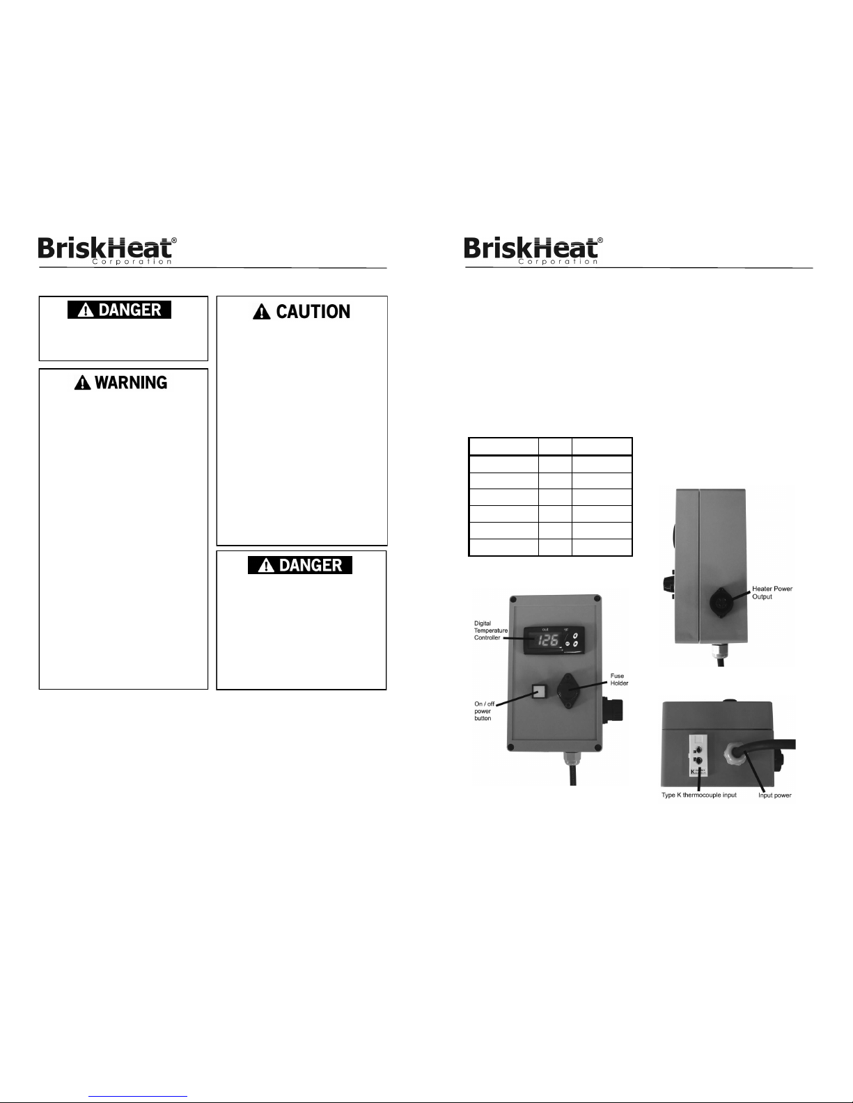
Part Number Volts Range
TTD175-K120 120 32 to 175°F
TTD175-K240 240 32 to 175°F
TTD500-K120 120 32 to 500°F
TTD500-K240 240 32 to 500°F
TTD999-K120 120 32 to 999°F
TTD999-K240 240 32 to 999°F
PRODUCT VIEWS
Side View
Front View
Bottom View

BriskHeat® Corporation. All rights reserved
5
TB4000 Bulb and Capillary
Temperature Controller
INSTALLATION OF MALE OUTPUT PLUG TO HEATER
Tools Needed
1/8” flathead screwdriver
Wire stripper
STEP 1: Lead Wire Preparation
Refer to Figure 1. Verify lead wire dimensions are within tolerances.
STEP 2: Assemble Plug
Verify that you have all components. Refer to Figure 2. Part “B” is a rubber
grommet. Select the correct size based on diameter of lead wire. See Figure 3.
Slide part “B” into part “C”. Attach part “A” to part “C”. Slide lead wires through
partial plug assembly.
Figure 1
Figure 2
STEP 3: Connect Lead Wires to Pins
Using a 1/8” flathead screwdriver, tighten correct lead wire with correct pin on
part “D”. Refer to Figure 4.
120V: Pin 1 and 2 are for the power leads. Pin is for the ground lead.
240V: Pin 1 and 3 are for the power leads. Pin is for the ground lead.
STEP 4: Finish Plug Assembly
Attach part “D” to part “C” and tighten. Tighten part “A” to part “C”.
Figure 3: “B” Figure 4
BriskHeat® Corporation. All rights reserved
6
TB4000 Bulb and Capillary
Temperature Controller
Read and understand this entire manual before
operating this controller.
INSTALLATION / OPERATING INSTRUCTIONS
Plug heater into the controller and the controller into its power source. Plug ther-
mocouple into thermocouple jack. For proper temperature control, place the
thermocouple sensing tip so that it touches the edge of the heater.
- Sensor must be in close proximity to the heater to prevent overheating.
- If heater is installed on a vertical surface, place sensor directly on lower
edge of heating blanket since heat naturally rises.
- Secure with one strip of aluminum adhesive tape.
Mount controller using mounting feet. For IBC / tote tank heating applications,
attach controller to IBC / tote tank using optional hanging bracket kit. Push illu-
minated power button “ON”. Refer to “Programming Instructions” for how to
program controller.
PROGRAMMING INSTRUCTIONS
VOLTAGE
120VAC; 240VAC
PARAMETER PROGRAMMING
• Press SET. SP text will appear on the display.
• Press SET again. The real value is shown on the display.
• The value can be modified with the UP and DOWN arrows.
• Press SET to enter any new values.
• Press SET and DOWN at the same time to quit programming or wait one
minute and the display will automatically exit programming mode.

BriskHeat® Corporation. All rights reserved
7
TB4000 Bulb and Capillary
Temperature Controller
Descripon Units Range
SP Set Point Degrees r1 to r2
r0 Dierenal or hysteresis Degrees 1 to 99°
r1 Low Value Set Point Degrees 0 to 999°
r2 High Value Set Point Degrees 0 to 999°
d0 Heang or Cooling Control Opon Ht/Co
c0 Min. Stop Time for Load Minutes 0 to 59
c2 Load Status During Probe Error 0/1 O/On
P1 Ambient Probe Adjustment Degrees -30° to 30°
P5 Ambient Probe Type Opon J, K, or S
P6 Probe Response Numeric 0 to 3
H5 Parameter Access Code Numeric *0 to 255*
A0 Alarm 1 Hysteresis Degrees 0 to 999°
A1 Alarm 1 Threshold Degrees 0 to 999°
A2 Alarm 1 Exclusion Time Seconds 0 to 999°
A3 Alarm 1 Conguraon Opon O, Lo, Hi
A4 Alarm 2 Hysteresis Degrees 0 to 999°
A5 Alarm 2 Threshold Degrees 0 to 999°
A6 Alarm 2 Exclusion Time Seconds 0 to 999°
A7 Alarm 2 Conguraon Opon O, Lo, Hi
Parameters
*Parameter Access Code is set to 0 as a factory default*
BriskHeat® Corporation. All rights reserved
8
TB4000 Bulb and Capillary
Temperature Controller
Parameter Descriptions
SP= Set Point-Desired Regulation Temperature
r0= Differential or Hysteresis
r1= Lower Set Point Limit
r2= Higher Set Point Limit
d0= Heating or Cooling Control-regulation cycles only performed,
neither defrosting nor continuous cycles exist. Heating: To
choose heating control: Set d0=Ht (The output is active when
TS1 (temperature of ambient probe) is less than or equal to
set point.) TS1<=SP. It then disconnects when TS1>=SP-r0.
Cooling: To choose cooling control: Set d0=Co (The output
is activated when TS1>=SP+r0.) The display will switch off
when TS1<=SP.
c0= Minimum Time Between Start to Stop
c2= Load Status during Probe Error. In the event of an open or
short-circuited probe, the unit will connect or disconnect the
load as defined by this parameter.
P1= Ambient Probe Calibration. Offset degrees to adjust ambient
probe. If the probe is not placed in the exact point that is to be
measured, use a standard thermometer and adjust the differ-
ence with parameter.
P5= Ambient Probe Type. Select between J, K, or S type thermo-
couple.
P6= Probe Response Rate (0 = 8 seconds, 1 = 4 seconds, 3 = 1
second)
H5= Access to Probe Parameters. (The code is set to 0 from the
factory.)
A0= Alarm 1 Hysteresis. The differential associated with A1 pa-
rameter.
A1= Alarm 1 Threshold. Number of degrees to the working set
point that initiates an alarm condition.
A2= Alarm 1 Exclusion Time. The amount of time the alarm is
disabled from instrument activation.

BriskHeat® Corporation. All rights reserved
9
TB4000 Bulb and Capillary
Temperature Controller
Parameter Descriptions Continued
A3= Alarm 1 Configuration. Determines the alarm type: A3=off
alarm is disabled; A3=Lo alarm is activated if the ambient
temperature >=SP+A1 and deactivated if <+SP+A1-A0;
A3=Hi alarm is activated if the ambient temperature
<=SP+A1 and deactivated if >+SP+A1-A0.
A4= Alarm 2 Hysteresis. The differential associated with A5 pa-
rameter
A5=Alarm 2 Threshold. Number of degrees to the working set
point that initiates an alarm condition.
A6= Alarm 2 Exclusion Time. The amount of time the alarm is
disabled from instrument activation
A7= Alarm 2 configuration. Determines the alarm type: A7=off
alarm is disabled; A7=Lo alarm is activated if the ambient
temperature >=SP+A5 and deactivated if <+SP+A5-A4;
A7=Hi alarm is active if the ambient temperature <=SP+A5
and deactivated if >+SP+A5-A4
Access to all code protected parameters
Press SET for 8 seconds. The access code value 0 is shown on
the display. (Unit comes with code set at 0 from factory)
With the UP and DOWN arrows, code can be set to user needs.
Press SET to enter the code. If code is correct, the first parameter
label is shown on the display (SP)
Move to the desired parameter with the UP and DOWN keys.
Press SET to view the value on the display.
The value can be modified with the UP and DOWN arrows.
Press SET to enter the value and exit to text parameter.
Repeat until all necessary parameters are modified.
Press SET and DOWN at the same time to quit programming or
wait one minute and the display will automatically exit program-
ming mode.
BriskHeat® Corporation. All rights reserved
10
TB4000 Bulb and Capillary
Temperature Controller
TROUBLESHOOTING GUIDE
Please read this guide prior to contacting BriskHeat®. This guide is designed
to answer the most commonly asked questions. If you are unable to identify
the problem or need additional assistance, please contact your local distributor
or BriskHeat® at 1-800-848-7673 (U.S. & Canada), 1-614-294-3376 (World
Controller does not function
1. Check fuse: Unplug the unit from its power source. Remove the fuse and
check its continuity. If the fuse is defective, replace it with an Class CC 15 amp
fuse. Fuses may be obtained from most electrical supply houses.
2. Check fuse position: Fuse is position specific. Ensure nipple of fuse is facing
down away from fuse cap.
3. Check power source: Using a voltmeter, test the power source and assure
correct voltage is present.
4. Check thermocouple: Using a thermocouple meter, test the sensor to assure
proper function.
Indicators
BUZZER
In the event of alarm or error condition, the internal buzzer is activated. To
silence the buzzer, press and hold the SET and Down keys for 2 seconds.
LED INDICATIONS
• OUT = Indicates that the heater is on.
DISPLAY MESSAGES
In normal operation, the sensor temperature will be shown on the display. In
case of alarm or error, the following messages will be shown:
• Er = Memory Error / Controller Error
• -- = Short-Circuit Thermocouple Error (Disconnects output).
• oo = Open Thermocouple Error (Disconnects output).
CONTROLLER OPERATION:
Once the controller reaches set point, the heater will turn off and will not turn
on again until the temperature falls 5°F below the set point.
The controller will sound an audible alarm if the temperature at the sensor
exceeds 15°F above the set-point.

BriskHeat® Corporation. All rights reserved
11
TB4000 Bulb and Capillary
Temperature Controller
Notes:
BriskHeat® Corporation. All rights reserved
12
TB4000 Bulb and Capillary
Temperature Controller
1055 Gibbard Ave, Columbus, OH 43201
Toll Free: 800-848-7673
Phone: 614-294-3376
Fax: 614-294-3807
Email: bhtsales1@briskheat.com
PN: 11692 Rev/ D
BriskHeat® warrants to the original purchaser for the period of
eighteen (18) months from date of shipment or twelve (12) months
from date of installation, whichever comes first. Contact factory at
1-800-848-7673 (toll free, U.S. / Canada) or 614-294-3376 for
complete details.
WARRANTY INFORMATION
Este manual sirve para los siguientes modelos
6
Tabla de contenidos
Otros manuales de Controladores de temperatura de BriskHeat

BriskHeat
BriskHeat HL101 Series Manual de usuario

BriskHeat
BriskHeat X2 Benchtop Manual de usuario

BriskHeat
BriskHeat SDX Manual de usuario

BriskHeat
BriskHeat SDCE Manual de usuario

BriskHeat
BriskHeat Centipede 2 Manual de usuario

BriskHeat
BriskHeat SDC Manual de usuario

BriskHeat
BriskHeat TC4000 Manual de usuario

BriskHeat
BriskHeat TB4000 Manual de usuario

BriskHeat
BriskHeat SDC Manual de usuario

BriskHeat
BriskHeat LYNX Manual de usuario


