Bogen PCM-CPU Manual de usuario

© 2001 Bogen Communications, Inc.
All rights reserved.
54-5945-01B 1010
Bogen Model PCMCPU
Central Processing Module for
Bogen's PCM2000 Zone Paging System

2
FCC Required Statements
WARNING:
Changes or modifications to this unit not expressly approved by the
party responsible for compliance could void the user's authority to operate the
equipment.
FCC Requirements
This equipment is component registered with the Federal Communications Com-
mission (FCC) in accordance with Part 68 of its rules. In compliance with the rules,
be advised of the following:
1. The Federal Communications Commission (FCC) has established Rules which
permit this device to be directly connected to the telephone network. Standard-
ized jacks are used for these connections. This equipment should not be used
on party lines or coin lines.
2. If this device is malfunctioning, it may also be causing harm to the telephone
network; this device should be disconnected until the source of the problem can
be determined and until repair has been made. If this is not done, the telephone
company may temporarily disconnect service.
3. The telephone company may make changes in its technical operations and pro-
cedures; if such changes affect the compatibility or use of this device, the tele-
phone company is required to give adequate notice of the changes.
4. If the telephone company requests information on what equipment is connected
to their lines, inform them of:
(a) The telephone number that this unit is connected to,
(b) The ringer equivalence number [1.3B]
(c) The USOC jack required [RJ11C], and
(d) The FCC Registration Number [US:CD2PA13BTAMB2]
Items (b) and (d) are indicated on a label affixed to the unit. The ringer equiva-
lence number (REN) is used to determine how many devices can be
connected to your telephone line. In most areas, the sum of the RENs of all de-
vices on any one line should not exceed five (5.0). If too many devices are at-
tached, they may not ring properly.
PCMCPU

3
Contents
Section 1: Overview
Description......................................................................................................4
PCM2000 System ..........................................................................................4
Voice Channel ................................................................................................4
Background Music (BGM) ..............................................................................5
Signaling ........................................................................................................5
Other Features................................................................................................5
Specialized Features ......................................................................................5
Section 2: Installation
Assembling Modules ..................................................................................6-7
Power..............................................................................................................8
System ID ......................................................................................................8
Program/Run Switch ......................................................................................8
Audio Connections..........................................................................................8
Low-Power BGM ............................................................................................8
High-Power BGM............................................................................................8
Emergency/Shift Change Trigger....................................................................8
AUX/GND Contacts ........................................................................................8
Section 3: System Expansion
Concept ..........................................................................................................9
Audio Wiring ..................................................................................................9
Data Link Wiring ............................................................................................9
System ID ....................................................................................................10
Section 4: Paging System Assemblies:
Applications and Illustrations
Introduction ..................................................................................................11
One-Way Paging System with Satellites ................................................12-13
Two-Way Talkback Paging System with Satellites ..................................14-15
3-Zone System w/ One-Way Paging & Single Amp BGM........................16-17
6-Zone System w/ One-Way Paging, Hi/Low Power & Local BGM ............18-19
9-Zone System w/ Talkback, Single Amp BGM, Hi/Low Power Zones ...... 20-21
PCMCPU

4
Section 1
Overview
Description
The Bogen Model PCMCPU is the microprocessor module for the Bogen PCM
Zone Paging System. One module is required per assembly (up to three PCMZPM
zone modules). The PCMCPU module provides power, data and audio connec-
tions for the PCM system.
The PCMCPU module is connected to other PCM modules electrically through in-
ternal cables. Modules are mechanically joined by sliding together interlocking tabs
and securing with a screw on the rear panel. The system is designed to be wall-
mounted with the modules side by side like books on a shelf, the PCMTIM is far left,
the PCMCPU is first from left and the (first) PCMZPM module is on the right.
(Arrange as shown in illustration on page 7.)
The PCMCPU module includes a set of DIP switches that set the System ID,
a POWER LED, a PROGRAM/RUN switch, a DATA LINK RCA jack (used to con-
nect to satellite systems), power in jack/terminals, and audio connections for PA, low-
power BGM, high-power BGM, emergency/shift change trigger and auxiliary contacts.
PCM2000 System
Minimum system configuration consists of three modules:
PCMCPU, PCMTIM, and PCMZPM provides 3 Zones of paging. To this, you can
add up two additional PCMZPM modules to a maximum of 9 zones. If more than
9 zones are required, satellite assemblies can be added to bring total capacity to
99 zones. Also a talkback module (PCMTBM) can be added for 2-way communi-
cations.The PCM2000 system provides the following features and functions:
Voice Channel
• Up to 99 zones of paging (in 3 zone increments) and sub-zone group paging
(up to 32 zone groups, each with up to 99 zones)
• Override paging (using loop start or contact closure)
• Talkback paging (centrally-amplified zones only)
• High-powered central paging (can be combined with Low Power Paging)
• Low-power paging to amplified speakers (can be combined with
High-Power Paging)
• Privacy beep on talkback zones
• Pre-announce tone
PCMCPU

5
Background Music (BGM)
• Low-power distributed (buffered for up to 50 amplified speakers)
• High-power, using dedicated BGM amplifier
• High-power using a single paging/BGM amplifier
• BGM disable to individual zones
• Local BGM input on each individual zone module
Signaling
• Night ringer (90V or contact closure activation)
• Code calling (2 types - echo & pattern)
• Emergency/shift change tone (tone and duration selectable)
Other Features
• DTMF setting of all operating parameters
• External C-form relay contacts
• Relay driver output per zone
• Non-volatile memory for setup data (no backup battery required)
• Talk/Talkback selection per zone
• Setup tone to assist in volume setting, etc.
Specialized Features
• PCMTBM Modules provide time-triggered signaling with built-in, real-time clock
• PCMTBM Module provides talkback paging
PCMCPU

6
Section 2
Installation
Assembling Modules
To assemble modules together, place them side by side starting with the left most
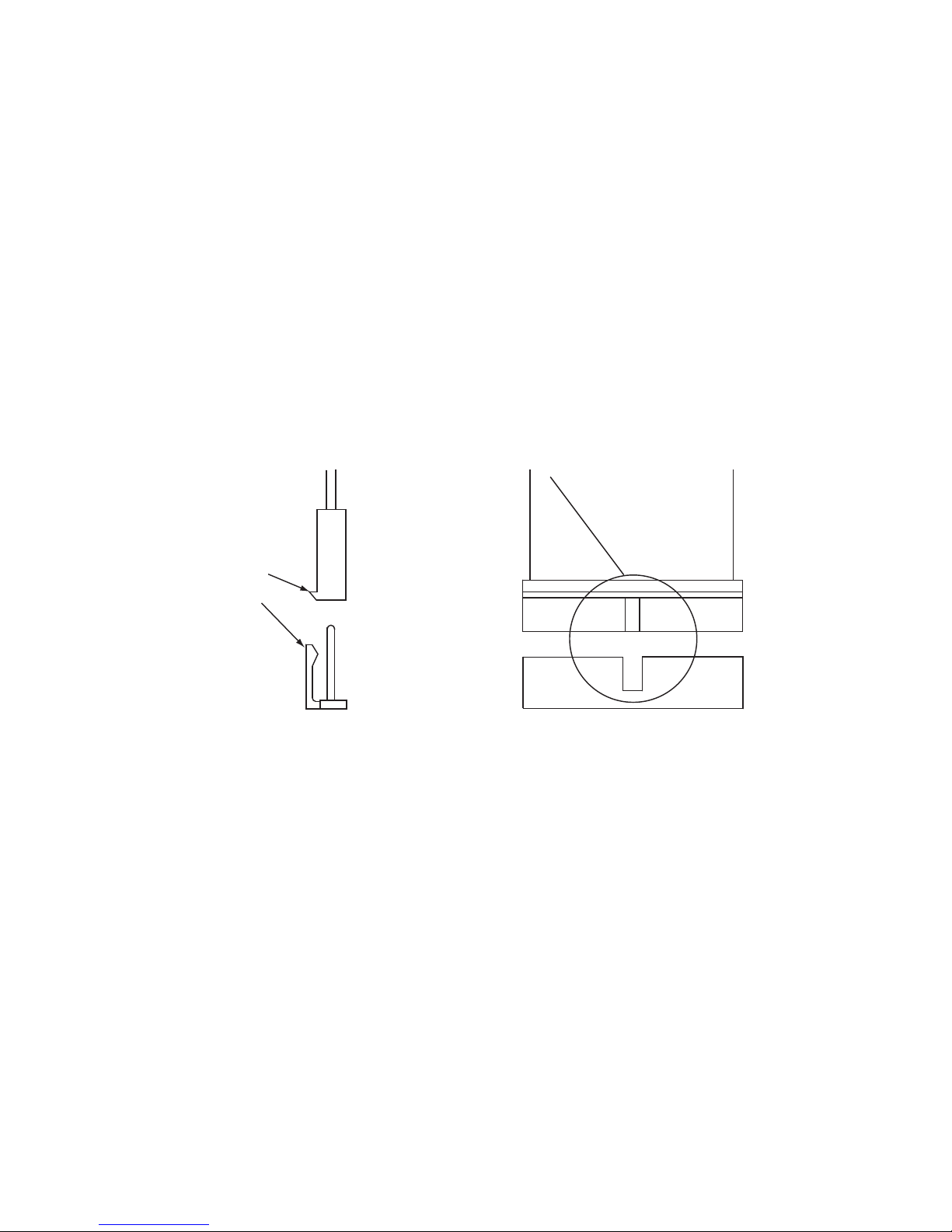
module of the assembly (for master system assembly, PCMCPU). Plug the ribbon
cable connector into its header (see drawing for orientation). Then plug the 6-pin
connector onto its header.
NOTE: It is very important to check for proper orientation of this connector
(see illustration).
NOTE: If the 6-pin connector is installed backwards, the power light on this mod-
ule (and possibly the entire assembly) will not light when powered up. Correct this
by separating the modules and locating the reversed 6-pin connector.
Place the modules close together and dress the connector cables away from the
sheet metal so that they will not get pinched. Push the two units together while
aligning the locking tabs on the top and bottom sides of the left unit with the lock-
ing slots on the right unit. At this point the left unit will be positioned slightly ahead
of the right unit. Now slide the left unit back against the right unit until the faces of
both units are even. Secure the two units together by tightening a screw into the
screw clamp tab in the back of the unit.
NOTE: It is usually easier to run the screw in and out of the screw clamp tab,
to cut a thread, before assembling the units together.
Align connectors
so locking ridge
faces header wall.
6-pin Connector
Align polarizing tab in slot
Ribbon Cable Connector
PCMCPU

7
Repeat the procedure for the rest of the modules to be included in the assembly.
The figure below shows the correct sequence of modules for a maximum assembly.
If certain modules are not used, remove them and maintain the order shown for
the rest of the modules.
NOTE: PCMTIM and PCMTBM are not used in satellite unit.
LOCKING
TAB
LOCKING
TAB
LOCKING
SLOT
LOCKING
SLOT
ALIGN
CONNECTORS
SO LOCKING
RIDGE FACES
HEADER WALL
ALIGN .
POLARIZING
TAB IN SLOT
SCREW CLAMP
TAB & SLOT
POWER
1.5A
GND
AUX
GND
S1
S2
S3
S4
0 1
SYS
ID
RUN
PROGRAM
DATA
LINK
12 VDC
1.5A
-
RT
IN
RT
IN
EM/SC
12VDC
LPBGM
HPBGM
+
POWER
RD COM
+
-
RD A
RD B
ZONE A
ZONE B
ZONE C
OFF ON
TALKBACK
RT
IN
RD C
LOCAL
BGM
ZONE A
+
-
ZONE B
+
-ZONE C
LPBGM
VOLUME
LO PWR
HI PWR
OUTPUT
BGM
OUT IN
PCM
ZPM
PCM
CPU
ZONE A
ZONE B
ZONE C
GLOBL BGM
+
_
PCM
TBM
POWER
VOLUME
TALKBACK
DELAY
OUT
RT
IN
RT
PA
PA
NOISE
REDUCTION
ON
OFF
RT
IN
PA
RT
OUT
PA
POWER
RD COM
+
-
RD A
RD B
ZONE A
ZONE B
ZONE C
OFF ON
TALKBACK
RT
IN
RD C
LOCAL
BGM
ZONE A
+
-
ZONE B
+
-ZONE C
LPBGM
VOLUME
LO PWR
HI PWR
OUTPUT
BGM
OUT IN
PCM
ZPM
ZONE A
ZONE B
ZONE C
GLOBL BGM
POWER
RD COM
+
-
RD A
RD B
ZONE A
ZONE B
ZONE C
OFF ON
TALKBACK
RT
IN
RD C
LOCAL
BGM
ZONE A
+
-
ZONE B
+
-ZONE C
LPBGM
VOLUME
LO PWR
HI PWR
OUTPUT
BGM
OUT IN
PCM
ZPM
ZONE A
ZONE B
ZONE C
GLOBL BGM
PCM
TIM
OPTIONAL OPTIONAL
PCMCPU

8
Power
The PCM system requires 12V DC 1.5A. Use the PCMPS2 power supply. Plug the
power supply into the POWER jack on the PCMCPU module. Power can also be
connected to the 12V DC terminals on the connector block.
For a system with no satellites, set SYS ID DIP switches on PCMCPU module to
the position shown. See section on System Expansion in this manual for addi-
tional information on setting system IDs in expanded systems.
Zone #s DIP Setting For SYS ID
S1 S2 S3 S4
Master 1 - 9 0 0 0 0
Program/Run Switch
The Program/Run switch must be set to the PROGRAM position during system
programming and the RUN position during normal operation. Refer to the instruc-
tions included with the PCMTIM module for programming instructions.
Audio Connections
Centralized amplifier connections are made to the screw terminals marked PA IN
and PA OUT on the PCMCPU module. Connect PA IN and RT (return) to the audio
input on the paging amplifier. Connect the high-power (70V) output of the amp to
the PA OUT and RT terminals.
Low-Power BGM
Connect BGM source to the LPBGM IN & RT terminals (Connect signal ground or
shield to RT terminals and the hot to IN). This provides low-level BGM signals to the
PCMZPM modules with LO PWR OUTPUT selected. This input is unbalanced.
High-Power BGM
Connect BGM source to the input of a 70V amplifier. Connect the high-power (70V)
output of the amplifier to the HPBGM IN & RT terminals (amplifier common should
connect to RT). This provides high-power background music signal to the PCMZPM
modules with HI PWR OUTPUT selected.
Emergency/Shift Change Trigger
External input control is available to trigger a tone signal from the PCM2000 over
the paging system. Shorting EM/SC to the GND terminal will produce a user-
programmed tone into a preselected group of zones. See Programming section of
the PCMTIM manual for information on programming the EM/SC feature.
AUX/GND Contacts
These contacts are used to synchronize with an external master clock. Shorting these
terminals resets the real time clock in the PCMTBM module to a user preset time. See
the PCMTIM manual Programming section for further information on this function.
ID
SYS
S1
S2
S3
S4
10
PCMCPU
System ID

9
Section 3
System Expansion
Concept
In situations where it is necessary to extend beyond 9 zones of paging, satellite
systems and a master must be used. Each satellite system is responsible for the
specific group of zones as determined by the setting of its SYS ID DIP switches.
The master system transmits its commands on the Data Link bus to all satellites at
the same time, but only the specifically addressed satellite responds.
NOTE: A satellite system consists of 1 PCMCPU module and 1 to 3 PCMZPM
modules. PCMTIM and PCMTBM modules are not used and will not work in a
satellite system.
Audio Wiring
Audio wiring is daisy-chained from one assembly to another. The illustration on
page 15 shows the daisy chain audio wiring between system assemblies (wiring to
the BGM sources is only done on the master system). The same wiring scheme is
used between adjacent assemblies.
Data Link Wiring
The DATA LINK ports of the system's PCMCPU modules are connected using RCA
cables. For a system with one satellite, a standard male-to-male RCA cable can be
used. For systems with more than one satellite, the recommended interconnecting
cable consists of a single female RCA connector with two male RCA connectors
(see illustration below). It is also recommended that the distance between adjacent
satellite systems does not exceed 3 feet, and that all DATA LINK connections are
securely made and well seated. Bad connections will result in operational failures
and/or inconsistent operation.
Connect to DATA COM port on
Master PCMCPU
Connect to DATA COM port on Satellite
PCMCPU.
This plug not used. This jack not used
on last Satellite.
PCMCPU

10
DIP Setting For SYS ID
Zone #'s S1 S2 S3 S4
Master 1 - 9 0 0 0 0
1 10 - 18 1 0 0 0
2 19 - 27 0 1 0 0
3 28 - 36 1 1 0 0
4 37 - 45 0 0 1 0
5 46 - 54 1 0 1 0
6 55 - 63 0 1 1 0
7 64 - 72 1 1 1 0
8 73 - 81 0 0 0 1
9 82 - 90 1 0 0 1
10 91 - 99 0 1 0 1
1 = On 0 = Off
ID
SYS
S1
S2
S3
S4
10
Satellite Zones & SYS ID Switch Positions
System ID
Once the satellite systems have been wired together, the satellite ID numbers can
be assigned. The ID for the master system (the one which has the PCMTIM module)
must be set to zero (all SYS ID switches set to "0"). Although satellite systems can
be numbered in any order, it is best to number them sequentially, starting with "1"
and following the way in which they are daisy-chained together. The table below
shows the SYS ID switch settings for the available satellite numbers and the zones
that each satellite is responsible for. After satellites have been numbered, you may
want to mark the actual zone numbers for each zone in the white area to the left of
the zone terminal screws. Use an indelible felt-tip marker. The lowest numbered
zone in the satellite system is the top zone in the PCMZPM module adjacent to the
PCMCPU module. The highest zone in the satellite is the bottom zone in the last
PCMZPM module.
After satellite systems have been wired and ID numbers assigned, the system can
be powered up. If it is necessary to change the ID number of a satellite after the
system has been powered, you must remove and then reapply power TO THAT
SATELLITE after changing switch settings.
PCMCPU
Satellite
Otros manuales para PCM-CPU
1
Tabla de contenidos
Otros manuales de Hardware de computadora de Bogen
Manuales populares de Hardware de computadora de otras marcas

EMC2
EMC2 VNX Series Manual del propietario

Panasonic
Panasonic DV0PM20105 Manual de usuario

Mitsubishi Electric
Mitsubishi Electric Q81BD-J61BT11 Manual de usuario

Gigabyte
Gigabyte B660M DS3H AX DDR4 Manual de usuario

Raidon
Raidon iT2300 Manual de usuario

National Instruments
National Instruments PXI-8186 Manual de usuario