BLAM Express EX 500 Manual de usuario

USER MANUAL
NOTICE D’UTILISATION
EX 500

TECHNICAL FEATURE
Compatible with OEM head units
• RCA low level inputs
• High level inputs
• RMS Power (4 Ω): 4x80 W
• RMS Power (2 Ω): 4x100 W
• Bridged RMS Power (4 Ω): 2x240 W
• RMS Power subwoofer channel (D class) : 200 W (4 Ω) / 300 W (2 Ω)
• Low pass crossover: 50 Hz – 250 Hz
• High pass crossover: 50 Hz – 3 kHz
• Signal/noise ratio > 90 dB
• Protections: short circuit / low impedance / heat protection
• External wired remote control
• Dimensions (L x W x H):
427.5 x 216 x 53 mm – 16.8’’ x 8.5’’ x 2.1’’
GB
2
CAUTION
Thank you for using the EX 500 amplifier, to ensure the best
performance from your amplifier, please read the Operating
Manual before using the amplifier.

3
POWER CONNECTIONS
Connect an empty fuse holder within 18” (45 cm) of the car battery,
and run 8 gauge (or heavier) cable from this fuse to the amplier
location. Then connect the fuse holder to the “BATT+”.
Connect the ground terminal to the closest point on the chassis of
the vehicle. Keep this ground wire to less than 39” (100 cm) in length.
Ensure that the contact surface is free of paint or rust so that the
connection between the terminal and the chassis is effective.
BATTERY
Ground
Headunit
GB
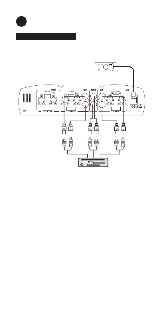
LOW LEVEL INPUT WIRING
Low-level (RCA) input wiring is preferred for best audio performance.
Always use a high-quality cable.
NOTE: do not connect BOTH the high level and low-level inputs from
your receiver to your amplier at the same time!
4
LEFT
RIGHT
HIGH INPUT
LEFT
RIGHT
HIGH INPUT
LEFT
RIGHT
HIGH INPUT
POWER
MIN MAX
Remote Level Control
Headunit
Install the remote control securely under
the dash or in a similar location where
using it will not distract the driver.

HIGH LEVEL INPUT WIRING
The high level input(s) should only be use if the RCA output are not
present, connect the speaker outputs from the receiver to the
high-level input connector of the amplier. Be sure to observe
polarity to avoid audio phase problems.
NOTE: do not connect BOTH the high-level signal and low-level inputs
from your receiver to your amplier at the same time!
5
LEFT
RIGHT
HIGH INPUT
LEFT
RIGHT
HIGH INPUT
LEFT
RIGHT
HIGH INPUT
To Speaker Terminals of
head unit
GREY L+
GREY/BLACK L-
R+ WHITE
R- WHITE/BLACK
GROUND
GREY L+
GREY/BLACK L-
R+ WHITE
R- WHITE/BLACK
GROUND
GREY L+
GREY/BLACK L-
R+ WHITE
R- WHITE/BLACK
GROUND
POWER
MIN MAX
Remote Level Control
Install the remote control securely under
the dash or in a similar location where
using it will not distract the driver.

GB
2-4 OHM SPEAKERS WIRING CONFIGURATION
4 OHM BRIDGED SPEAKERS WIRING CONFIGURATION
6
4 Ω Minimum bridged
speakers
++
+
2-4 Ω Subwoofer
2-4 Ω Speakers
+
+
+
+
+

TROUBLE SHOOTING
This amplier has multi-layer protection features to prevent
damage from misuse or faulty conditions to ensure long lasting life
of your investment. If the unit senses excessive heat, short circuited
speakers, overload, or voltage uctuation outside of the working
range the protection indicator light will turn red and the unit will
turn off. In order to solve this problem, you should turn all levels
down, power off the unit, then carefully check the installation for
wiring mistakes or shorts. If the amplier is excessively warm the
protection light will not turn on as the unit will turn off to protect
itself from overheating. Let the unit cool down for 30 minutes and
try again. If the unit work, try moving the amplier or make sure
nothing is covering it so it can vent heat off of the heatsink. Before
you remove or uninstall the amplier, refer to the list below for
suggested solutions.
Amplifier doesn’t turn on or not output:
• Check the fuse(s), not just visually , but with a continuity meter
and all 12+ volt, remov e and ground connection. It is possible f or
a fuse to have poor internal connections, take the fuse out of the
holder for the testing.
• Check the input signal from the source unit using an AC voltmeter
to measure the voltage while it’s being played. The voltage should
be from 0.5 to 15 volts from the RCA cables.
• Check the putput of the amplier, test for output at the speaker
output of the amplier.
• Check to ensur e that the speak er wires are making a good
connection to the amplier and the subwoof ers.
Amplifier goes into protection:
• Check the chassis ground connections.
• Check amplier controls for errors, input level or crossover
setting.
• Check the speaker wires for a possible short, either between the
positive and negative leads or between a speaker lead and the
vehicle’s chassis ground.
• Check the nominal load impedance to verify that the amplier is
driving a load equal or greater than 2 ohm.
• Check the input signal cables to make sure signal is present at
the amplier inputs and the cables are not pinched or loose.
Ot may be helpful to try a different set of cables/or a different
signal source to be sure.
• Check speaker wiring for reverse polarity .
7

CARACTÉRISTIQUES TECHNIQUES
Compatible avec les autoradios d’origine
• Entrées RCA bas niveau
• Entrées haut-niveau
• Puissance RMS (4 Ω) : 4x80 W
• Puissance RMS (2 Ω) : 4x100 W
• Puissance RMS bridge (4 Ω) : 2x240 W
• Puissance RMS canal subwoofer (Class D) : 200 W (4 Ω) / 300 W (2 Ω)
• Filtre passe-bas : 50 Hz – 250 Hz
• Filtre passe-haut : 50 Hz – 3 kHz
• Rapport signal/bruit > 90 dB
• Protections : court-circuit / impédance basse / protection
thermique
• Télécommande laire fournie
• Dimensions (L x l x H) :
427.5 x 216 x 53 – 16.8’’ x 8.5’’ x 2.1’’
F
8
MISE EN GARDE
Merci d’utiliser l’amplificateur BLAM EX 500. Afin de garantir
les meilleures performances de votre amplificateur, nous
vous recommandons de lire ce manuel avant d’utiliser
l’amplificateur.

CONNEXION DE L’ALIMENTATION
Connection à la batterie (+12 Volts) : Connectez un câble de 8mm2
minimum avec un porte-fusible placé à moins de 45 cm de la
batterie de la voiture et reliez le à la connexion “BATT +”.
Connectez la masse (-) au châssis du véhicule au point le plus
proche. Gardez ce l de masse d’une longueur inférieure à un
mètre. Utilisez un câble de 8mm2 (minimum) (AWG 8). S’assurer que
la surface de contact est exempt de peinture ou de rouille an que
le connexion entre la cosse et le chassis soit efcace.
9
BATTERIE
Masse
Autoradio

F
CÂBLAGE DES ENTRÉES BAS NIVEAU
Les entrées bas niveau (RCA) sont préférables pour de meilleures
performances audio, si votre autoradio est équipé de sorties RCA. Il
est recommandé d’utiliser un câble de bonne qualité.
REMARQUES : Ne connectez jamais les entrées haut niveau et bas
niveau en même temps.
10
LEFT
RIGHT
HIGH INPUT
LEFT
RIGHT
HIGH INPUT
LEFT
RIGHT
HIGH INPUT
POWER
MIN MAX
Télécommande
Autoradio
Fixez solidement sous le tableau de
bord de manière à ce que la
télécommande soit facilement
accessible.
Tabla de contenidos
Idiomas:
Otros manuales de Amplificador de BLAM


