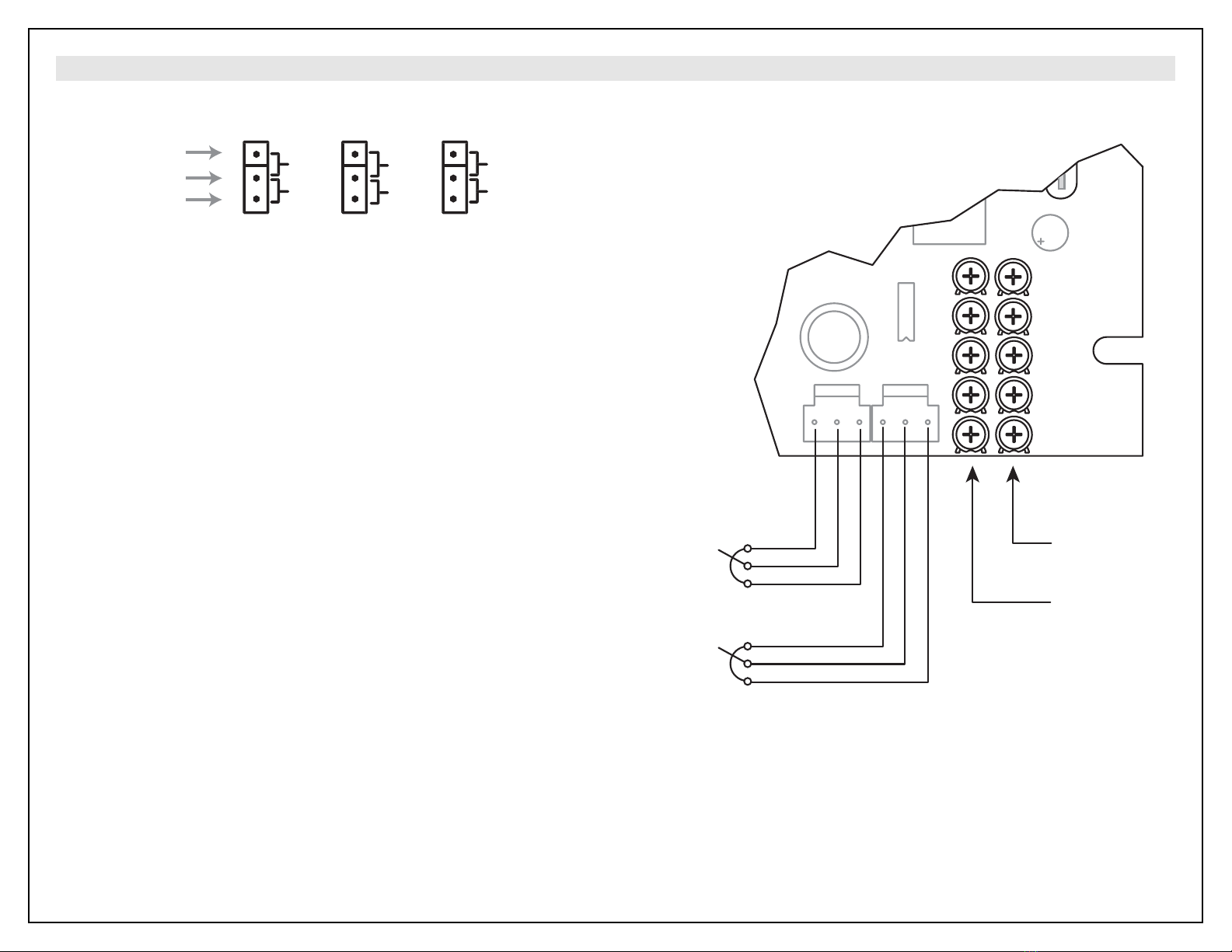
CALIBRATION / OPERATION
INDEPENDENT MODE (Jumper on pins 1 & 2 of J3)
There are two sets of potentiometers independently used to adjust each motor operation. Each set
consists of five on board trimmer potentiometers and one external potentiometer (commonly called
SPEED POT). To calibrate one side (A or B), use the following procedure:
1. Turn the SPEED POTENTIOMETER A (B) to full CCW. Use MIN SPEED A (B) trimmer
potentiometer to adjust minimum speed for motor A (B).
2. Turn the SPEED POTENTIOMETER A (B) to full CW. Use MAX SPEED A (B) trimmer
potentiometer to adjust maximum speed for motor A (B). Repeat steps 1 and 2 a few times due
to a level of interaction between MIN SPEED and MAX SPEED pots.
3. Set the CUR LIM A (B) to full CCW. Turn the SPEED POTENTIOMETER A (B) to full CW. Stall
the motor shaft and turn the CUR LIM A (B) CW until the desired current limit is reached.
4. Set the IR COMP A (B) to full CCW. Set the motor speed at approximately half of the rated
speed. Load motor to its full load. Keep turning the IR COMP CW until the speed equals the no
load speed.
5. Use ACC/DEC A (B) trimmer potentiometer to adjust acceleration (deceleration) ramp time.
RATIO MODE (Jumper on pins 2 & 3 of J3)
In RATIO MODE, SPEED POT A is used to adjust the speed of both motors, while SPEED POT B sets
the ratio between speeds. Turning the SPEED POT B CW will increase speed of motor B thus increasing
the ratio speed B/speed A. MIN SPEED B and MAX SPEED B are now used to adjust minimum and
maximum ratio.
TORQUE MODE (Jumper on pins 1 & 2 of J4)
TORQUE MODE regulates motor current (torque). In TORQUE MODE, the external potentiometer A (B)
sets the torque reference for Motor A (B) and the CUR LIM trimmer potentiometer A (B) sets the speed
limit for Motor A (B).
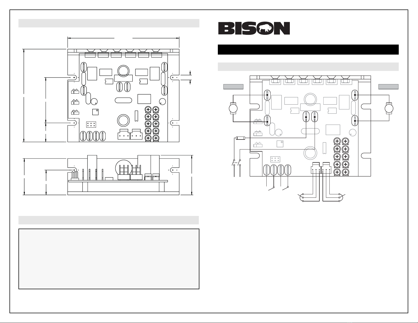
STOPPING: DECEL vs. COAST (J5)
There are two methods of stopping: DECEL and COAST.
DECEL - Placing a jumper on pins 1 and 2 of J5 and closing the inhibit terminals will cause the motor
to decelerate at a rate set by ACC/DEC pot.
COAST - Placing a jumper on pins 2 and 3 of J5 and closing the inhibit terminals will stop the
application of voltage to the motor, causing the motor to coast to a stop. This option is also
set for both motors simultaneously.
* NOTE: Deceleration time is a function of load inertia and friction. High inertia loads will decelerate
slower than high frictional loads.
Rotation: CW = Clockwise CCW = Counterclockwise
Bison Gear & Engineering Corp.
3850 Ohio Ave. -- St. Charles, IL 60174
Phone: 1-800-AT-BISON
www.bisongear.com
Document Number: 250-0415; Revision 0 -- May 2006
The Company warrants to the Buyer the products sold hereunder to be free of defects in material and workmanship under normal use and service for a
period of one (1) year from the date of shipment. The obligation of the Company under this warranty is limited to repair or replacing at its option, any part
or parts, which upon examination shall disclose to the reasonable satisfaction of the Company to have been defective in material or workmanship. Buyer
must return the products to the Company’s factory, shipping charges prepaid, and with complete information as to alleged defects and the installation,
operation and service of the products. Except as otherwise expressly stated herein the Company makes no representation of warranty of any kind, express
or implied, as to merchantability, fitness for a particular purpose, or any other matter with respect to the products sold hereunder.