BIGTREETECH
2/ 19
Contents
Contents................................................................................................................................................ 2
Revisions............................................................................................................................................... 3
Ⅰ. Brief Instruction............................................................................................................................. 4
1.1 Features.................................................................................................................................. 4
1.2 Parameters............................................................................................................................. 5
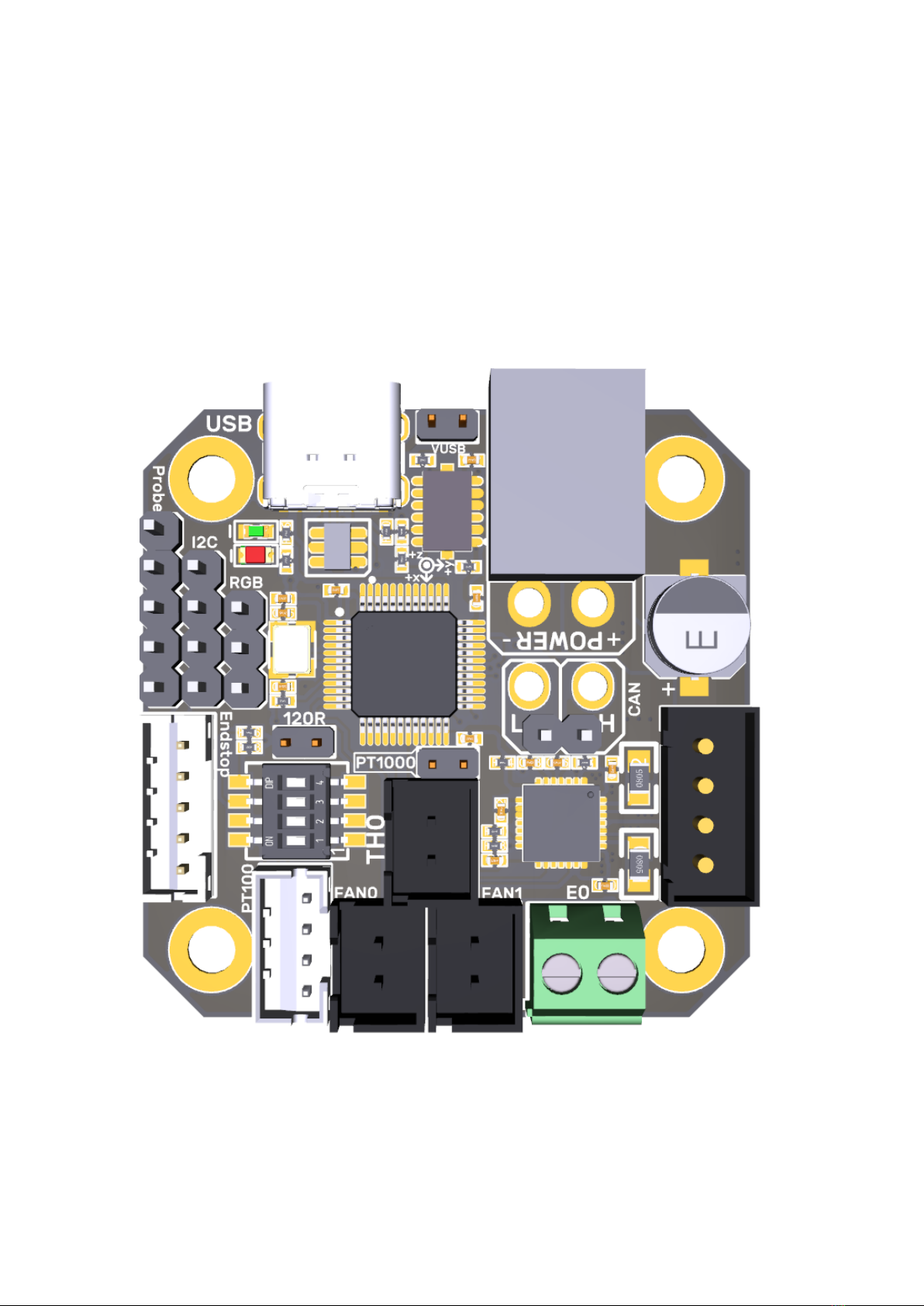
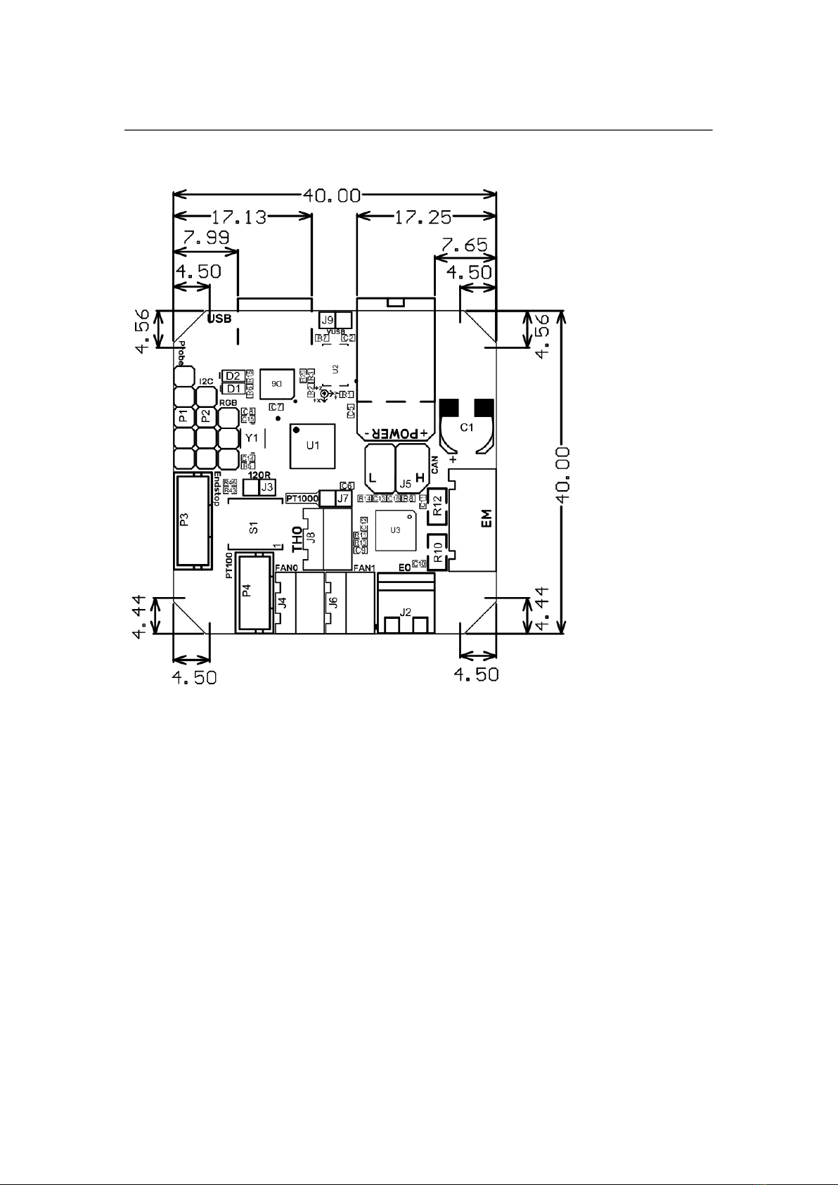
1. External Dimensions: 40mm x 40mm. For further details please read: BIGTREETECH
EBB36 CAN V1.0-SIZE.pdf........................................................................................................ 5
4. Input Voltage: DC12V-DC24V 9A........................................................................................... 5
5. Logic Voltage: DC 3.3V............................................................................................................ 5
6. Heating Interface: Heating Rod (E0), maximum output current: 5A.................................. 5
7. Onboard Sensor:ADXL345..................................................................................................... 5
8. Fan Interfaces: Two CNC Fans (FAN0, FAN1)..................................................................... 5
9. Maximum Output Current of Fan Interface: 1A, peak value 1.5A...................................... 5
10. Expansion Interfaces: EndStop, I2C, Probe, RGB, PT100/PT1000, USB Interface,
CAN Interface ................................................................................................................................ 5
11. Motor Drive: Onboard TMC2209.......................................................................................... 5
12. Driver Working Mode: UART................................................................................................. 5
13. Stepper Motor Interface: EM................................................................................................. 5
14. Temperature Sensor Interface(Optional): 1 channel 100K NTC or PT1000 (TH0), 1
channel PT100/PT1000................................................................................................................ 5
15. USB Communication Interface: USB-Type-C..................................................................... 5
16. DCDC 5V Maximum Output Current: 1A............................................................................. 5
1.3 Firmware................................................................................................................................. 5
1.4 Size Diagram.......................................................................................................................... 6
II. Peripheral interface........................................................................................................................ 7
2.1 Pin............................................................................................................................................. 7
III. Introduction of Interface.............................................................................................................. 8
3.1 USB Power Supply............................................................................................................... 8
3.2 100K NTC or PT1000 Settings........................................................................................... 8
3.3 Connection with BL-Touch............................................................................................... 10
3.4 Connection with Filament Broke Detection................................................................. 11
3.5 Connection with RGB........................................................................................................ 11
IV. Klipper............................................................................................................................................ 12
4.1 Compile Firmware.............................................................................................................. 12
4.2 Update Firmware................................................................................................................. 13
4.3 CANBus Configuration...................................................................................................... 15
4.3.1 Use with BIGTREETECH U2C Module................................................................ 15
4.3.2 Use with BIGTREETECH RPI-CAN HAT Module.............................................. 16
4.4 Klipper Configuration........................................................................................................ 18
V. Cautions.......................................................................................................................................... 19
VI. FAQ ................................................................................................................................................. 19