Biasi MULTIPOINT 14S Manual de usuario

User manual and
installation
instructions
MULTIPOINT

- 2 -
WARNING
WARNING
This manual contains data and information for both the user and the installer.
The user should look at the following chapters in particular: General warnings and safety, Flue gas
device, Control panel.
Please keep these instructions safe near the unit or gas meter for future use.
DANGER: Instructions marked with this symbol must be observed to prevent me-
chanical or generic accidents (e.g. injuries or bruises).
DANGER: Instructions marked with this symbol must be observed to avoid electri-
cal accidents (electrocution).
DANGER: Instructions marked with this symbol must be observed to avoid the dan-
ger of fire or explosions.
DANGER: Instructions marked with this symbol must be observed to avoid heat-re-
lated accidents (burns).
WARNING: Instructions marked with this symbol must be observed to avoid mal-
functions and/or material damage to the unit or other items.
WARNING: Instructions marked with this symbol contain important information
that must be read carefully.

- 3 -
WARNING
GENERAL WARNINGS
The instructions manual forms an integral part of the product and therefore must be carefully re-
tained and always kept with the unit; if lost or damaged, a copy of these may be downloaded from
the manufacturers web site www.Biasi.co.uk.
Installation of the unit and any other service or maintenance operation must be carried
out by a Gas Safe registered installer.
The unit must be used for the purpose envisaged by the manufacturer. No contractual and
extra-contractual responsibility can be taken for damage caused to people, animals or things,
as a result of installation, regulation and maintenance errors or improper use.
The safety or automatic regulation devices of the unit must not be modified.
This unit is used to produce hot water, it must therefore be connected to a domestic hot
water distribution network compatible with its performance and power.
In the event of a water leak, turn off the water supply and promptly notify your Gas Safe reg-
istered installer.
If away for a long time, turn off the gas supply. If there is the risk of freezing, empty the water
heater of the water it contains.
In the event of a fault and/or poor operation of the unit, turn it off, refraining from any at-
tempt to repair it or any direct intervention.
Maintenance of the unit must be carried out at least once a year: this may be undertaken by
any Gas Safe registered engineer.
BASIC SAFETY RULES
The use of the unit requires strict observance of some basic safety rules.
Do not use the device for purposes other than those for which it is designed.
It is absolutely prohibited to obstruct the flue terminal grills and the ventilation opening of
the room in which the unit is installed, with rags, papers or anything else.
If a smell of gas is detected, do NOT activate electric switches, the telephone and any other
object that might cause a spark. Air the room by throwing doors and windows wide open and
turn off the gas at the mains. Contact the national gas emergency helpline on 0800 111999.
Do not rest objects on the unit.
Do not leave containers and flammable substances in the room where the unit is installed.
Any attempt at repair is prohibited in the event of a fault and/or poor operation of the unit.
Use of the unit by children or inexperienced people is prohibited.
Tampering with the sealed elements is prohibited.

- 4 -
WARNING
Declaration of compliance
The undersigned BSG Caldaie a Gas S.p.A., legal office in Pordenone (Italy) - Via Pravolton, 1/b,
holder of EC CERTIFICATE for the products listed below,
DECLARES THAT THE UNITS
Instant gas water heater
Model Certification code
MULTIPOINT 14S SV14S
MULTIPOINT 16S SV16S
whose registration numbers are shown on the unit's data plate, comply with the following Euro-
pean Directives:
• Regulation (EU) 2016/426 on appliances burning gaseous fuels
• Efficiency Directive 92/42/EEC
• Electromagnetic Compatibility Directive 2014/30/EU
• Low Voltage Directive 2014/35/EU
• Ecodesign Requirements Directive 2009/125/EC
Furthermore, the units are built in compliance with accepted standards
and built pursuant to the technical safety regulations, in compliance
with the technical legislation in force, as required by art. 7 of Law 46 of
5 March 1990.

- 5 -
TABLE OF CONTENTS
1 FEATURES AND BENEFITS .................6
2 TECHNICAL SPECIFICATIONS ..............7
2.1 Technical Data .................................7
2.2 Electrical diagram..............................9
2.3 Parts 14S - 16S ................................10
2.4 Dimensions 14S - 16S .........................11
3 HOW TO USE .............................12
3.1 Display operation .............................12
3.2 Preparation before ignition....................13
3.3 Temperature Setting ..........................13
3.4 Ignition & Water Outlet........................13
3.5 Use function mode............................14
3.6 Instant hot water production and real time
gas consumption display......................14
3.7 Check the cumulative amount of gas
and water.....................................15
4 SAFETY CAUTIONS . . . . . . . . . . . . . . . . . . . . . . . 15
4.1 Prevention of freezing.........................15
4.2 Gas accident prevention ......................16
4.3 Fire prevention ...............................17
4.4 Carbon Monoxide toxicosis prevention ........17
4.5 Abnormal conditions..........................17
4.6 Scald prevention..............................17
5 INSTALLATION ...........................18
5.1 Packaging and accessories ....................18
5.2 Installation requirements......................18
5.3 Installation method ...........................19
5.4 Conversion instructions .......................23
6 MAINTENANCE...........................28
6.1 Trouble-shooting guidance ...................29
6.2 Explanation of the Error Codes ................30
7 BOILER DISPOSAL AND RECYCLING . . . . . . . 31
8 WARRANTY CONDITIONS.................32
9 BENCHMARK COMMISSIONING &
WARRANTY VALIDATION SERVICE
RECORD .................................33
Gas fired continuous flow water heater
commissioning checklist ......................34
Service record ................................35
Model Certification code
MULTIPOINT 14S SV14S
MULTIPOINT 16S SV16S

- 6 -
USE
DESCRIPTION OF UNIT
1 FEATURES AND BENEFITS
Micro-computer intelligent control system
The core component of the gas water heater
is a micro computer intelligent control system,
which is one of today’s most advanced mecha-
tronic technology. The CPU chipset can ana-
lyze automatically and set the optimal working
parameter rapidly according to different data
such as the flowing water quantity, the pres-
sure situation and the actual inlet water tem-
perature.
Digital control for automatic constant tem-
perature of outlet water
This function is to monitor the outlet water
temperature by a temperature sensor and to
transfer the information to the micro-comput-
er, so that the micro-computer can adjust the
gas and air supply quantity to guarantee the
constant outlet water temperature according
to the temperature set by the user and the ac-
tual inlet water temperature automatically.
Pressure
The lowest start-up water pressure of this
product could reach 0.02 MPa (0.2 bar) (or a
minimum flow rate of 2.5 L/min), so it could
also be used in the residence area with low
pressure.
"AI" Artificial Intelligent Memory Function
The water heater remembers the last set point
temperature removing a need to re set every
time the unit is activated.
Energy saving
This product has advanced technologies
called Strengthened Combustion and Forced
Combustion.
These features aim to make the best use of
heat energy with high working efficiency.
Set temperature by touch
You can set the required temperature easily by
touching the digital display. The temperature
range is from 35°C to 65°C.
Multiple safety protection
This product has built in safety protection, this
includes self-check protection, flame-out pro-
tection, over-heat protection, accidental pow-
er-cut protection, fan breakdown protection,
electric overload protection, electric leakage
protection, high wind pressure protection and
over temperature protection.
Tips
The above conclusion comes from the safety
protection test under lab conditions.
It may be affected by the surroundings in its
actual place of installation. Thus, please use
the product in proper conditions.

- 7 -
USE
DESCRIPTION OF UNIT
2 TECHNICAL SPECIFICATIONS
2.1 Technical Data
Model MULTIPOINT 14S MULTIPOINT 16S
Nominal heat input (Hi) kW 28.0 30.0
Minimum heat input (Hi)
G20 kW 9.0 9.5
G30 kW 9.0 9.5
G31 kW 8.0 8.5
Nominal heat output
G20 kW 25.4 27.4
G30 kW 25.4 27.8
G31 kW 25.4 27.8
Minimum heat output
G20 kW 8.2 8.7
G30 kW 8.3 8.9
G31 kW 7.4 7.9
Appliance type C13-33
Gas type 2H-G20-20mbar / 3B-G30-30mbar / 3P-G31-37mbar
Gas category II2H3P / II2H3B/P
Nom. gas supply pressures
G20 Pa-mbar 2000 - 20
G30 Pa-mbar 2900 - 29
G31 Pa-mbar 3700 - 37
Min. gas supply pressures
G20 Pa-mbar 1700 - 17
G30 Pa-mbar 2000 - 20
G31 Pa-mbar 2500 - 25
Max. gas supply pressures
G20 Pa-mbar 2500 - 25
G30 Pa-mbar 3500 - 35
G31 Pa-mbar 4500 - 45
Maximum gas flow rate (Q.nom.)(Hi)
G20 m3/h 2.96 3.17
G30 kg/h 2.21 2.37
G31 kg/h 2.18 2.33
Minimum gas flow rate (Q.min.)(Hi)
G20 m3/h 0.95 1.01
G30 kg/h 0.71 0.75
G31 kg/h 0.7 0.74
Max. flue gas temperature at 60°/80°C
G20 °C 118 118
Min. flue gas temperature at 60°/80°C
G20 °C 65 65
Max. flue gas mass flow rate
G20 kg/s 0.0215 0.0230
Min. flue gas mass flow rate
G20 kg/s 0.0045 0.0050

- 8 -
USE
DESCRIPTION OF UNIT
Max. air mass flow rate
G20 kg/s 0.0215 0.0224
Min. air mass flow rate
G20 kg/s 0.0047 0.0048
CO2 content (Nominal heat input)
G20 % 5.16 5.16
O2 content (Nominal heat input)
G20 % 11.7 11.7
CO content (Nominal heat input)
G20 ppm 227 229
NOx class
6
Weighted NOx
ppm 17.98 30.53
Max. flow rate (rise 25 °c)
kg/min 14.0 16.0
Max. water pressure (Pw) bar 10 10
Min. water pressure (Pw) bar 0.2 0.2
Electrical power supply
230 V ~ 50 Hz
Degree of electrical protection
IPX4 IPX4
Ignition method
Water control automatic pules ignition
Destination country
GB - IE
Gas inlet joint
G 1/2 G 1/2
Cold water inlet joint
G 1/2 G 1/2
Hot water outlet joint
G 1/2 G 1/2
Flue duct diameter
mm Ø 60 x Ø 100 Ø 60 x Ø 100
ErP Data MULTIPOINT 14S MULTIPOINT 16S
Declare load profile XL XL
Water heating energy efficiency (ηWH) % 84.0 80.5
Water heating energy efficiency class A A
Daily gas consumption (corrected) kWh 23.583 24.845
Daily electrical consumption (corrected) kWh 0.064 0.064
Annual fuel consumption AFC (GJ) 18 19
Annual electricity consumption AEC (kWh) 14 14
NOx
mg/kWh 29 47
Indoor sound power level (LWA) dB 61 63
G20 Hi. 34,02 MJ/m3(15°C, 1013,25 mbar)
G30 Hi. 45,65 MJ/kg (15°C, 1013,25 mbar)
G31 Hi. 46,34 MJ/kg (15°C, 1013,25 mbar)
1 mbar corresponds to approx. 10 mm H20

- 9 -
USE
DESCRIPTION OF UNIT
2.2 Electrical diagram
Figure 2.1
1 Gas separate valve 1
2 Gas proportional valve
3 Thermostat
4 Main board
5 Direct current fan
6 Power cord
7 Flame detector
8 Igniter
9 Earth
10 Display
11 Water inlet temperature sensor
12 Water outlet temperature sensor
13 Water flow sensor
14 Gas separate valve 3
15 Main gas valve
16 Gas separate valve 2
GND
1
2
3
5
4
6
7
8
9
10
11
12
1316 1415
- 10 -
USE
DESCRIPTION OF UNIT
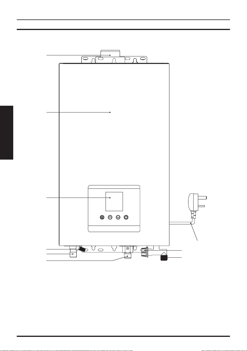
2.3 Parts 14S - 16S
Figure 2.2
1 Flue duct connector
2 Front panel
3 Display and control panel
4 Safety valve discharge
5 Hot water outlet
6 Gas inlet
7 Cold water inlet
8 Cold water inlet filter
9 Power cord
1
2
3
5
48
9
7
6
Este manual sirve para los siguientes modelos
3
Tabla de contenidos
Manuales populares de Calentador de otras marcas


Empire Heating Systems
Empire Heating Systems WCC65 Manual de usuario

Wetekom
Wetekom 92 86 43 Manual de usuario

Desa
Desa SPC170-F Manual de usuario

Watlow
Watlow Watrod Electric Tubular Heaters Manual de usuario

Haverland
Haverland ECO-DRY GPS Series Manual de lista de piezas

Stelpro
Stelpro ASILVC2060 Series Manual de usuario