BGS technic 40108 Manual de usuario

Art. 40108
Ignition Timing Light
I. Introduction for all Parts of the Timing Light
1. Xenon lamp (light the timing mark during checking the timing)
2. Flash frequency light switch (press this switch, the flash frequency light begins to flash, when
loosen, the flash stops)
3. Inductive signal pickup device (connect high voltage wire of cylinder 1)
4. Red battery jar clip (connect the battery anode + )
5. Black battery jar clip (connect the battery cathode - )
II. Preparation before the use of the timing light
2.1. Before any test, check carefully and eliminate all mechanical trouble. Loose connection or
damage of the pipe, wire, and connector will result in abnormal operation of the engine.
2.2. Follow the repair manual, check whether the vacuum pipeline, wire, and wire bunch connector
are correctly connected, then check the following parts: all liquid level, spark plug and high
voltage wire of the spark plug, air filter, vacuum pipeline, belt, circuit, circuit connector
2.3. Check the preparation of the ignition timing engine:
2.3.1 Before checking the ignition timing, make preparations of the engine, check the discharge
control plate of this vehicle or the test procedure and technical requirement for the ignition
timing in the repair manual. The discharge control plate of the vehicle is inside the engine
chamber, the usual position is: the back of the engine hood, the engine bulkhead, the top of
the valve chamber cover or near the engine hood lock.
2.3.2 Make the following preparations at least: Find the timing scale and the position of the indicator.
The timing scale and the indicator are usually at the crank pulley, crankshaft vibration damper
(at the front of the engine) or the flywheel (between the engine and the transmission), etc. (see
Fig. 2)
Three of many marking types
some marks on
crankshaft case and
one mark on crankshaft pulley
one TDC mark on
crankshaft pulley and
crankshaft case
some marks on
crankshaft pulley and one
mark on crankshaft case
The timing scale and the indicator should be clean and clear. Apply chalk dust on them if necessary.
All the spark plugs work normally, the gap between the electrodes is correct. Start the engine, run to
the normal working temperature. Shut down the engine before connecting the timing light.
F
ig. 2.1
F
ig. 2.2
F
ig. 2.3
III. Connecting the timing light
In order to ensure safety and reliable operation of the timing light, connect according to the following
steps:
Warning: keep hand, timing light, connecting wire and the signal pickup device away from the running
parts and the high temperature surface of the engine. No smoking.
3.1. Close the ignition switch. Never connect the timing light when the engine is running or the
ignition switch is turned on.
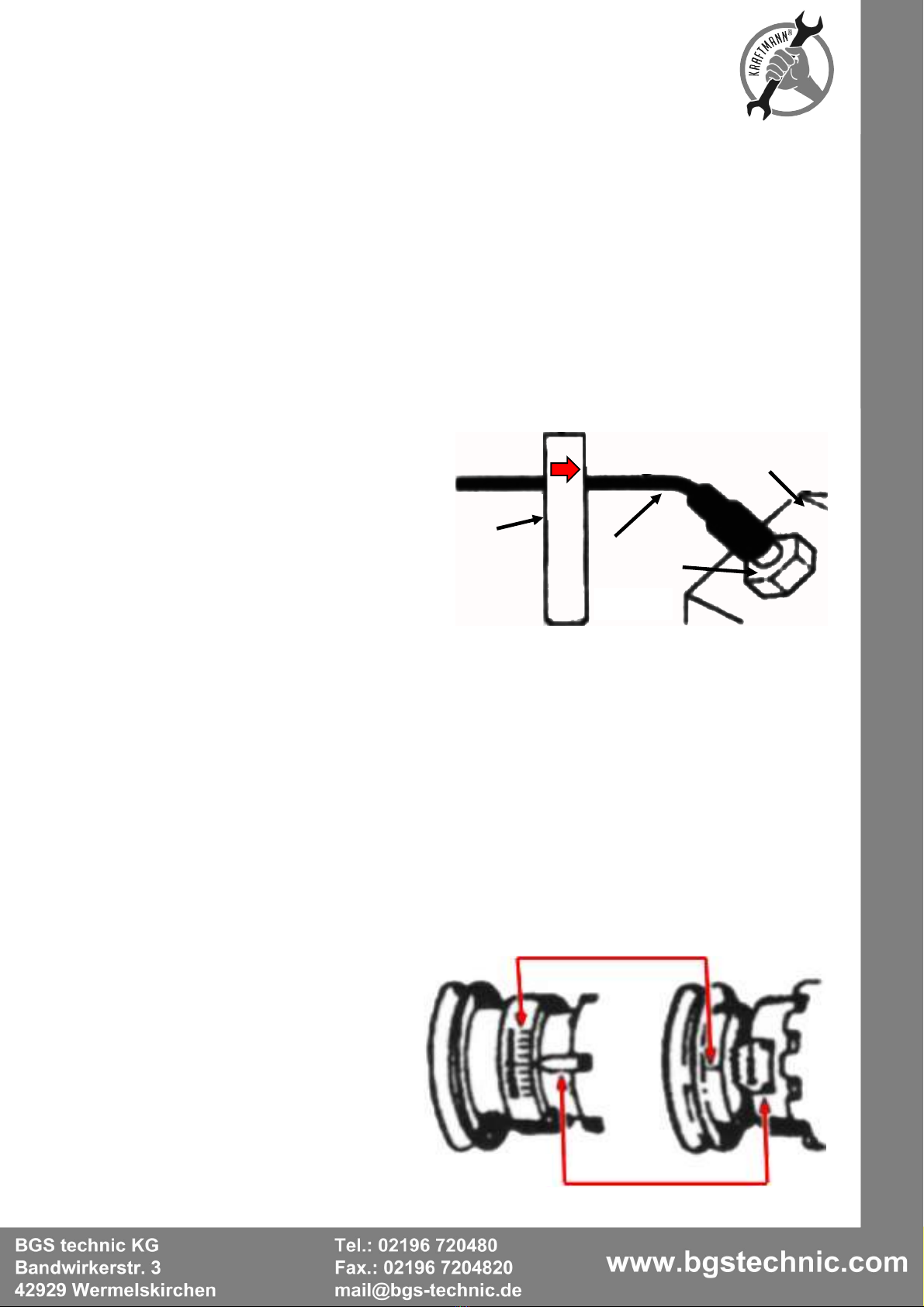
3.2. Clip the inductive signal pickup device to the high voltage wire of cylinder 1.(See Fig 3) Make
sure that the signal pickup device doesn't touch the discharge branch pipe or other parts of the
engine, as temperature on these parts can be very high when the engine is running, which may
damage the signal pickup device.
3.3. Clamp the battery jar clip at the battery jar inside the vehicle.
The red clip connects the anode (+)
The black clip connects the cathode (-)
Connection of the inductive signal pickup device and the high voltage wire
1 Inductive signal pickup device
2 High voltage wire of first cylinder
3 Spark plug of first cylinder
3 Engine
IV. Inspection of the basic ignition timing
Note: For some systems, before checking or adjusting the ignition time according to instructions,
some special elements should be unplugged, jump connected or grounded. If it's not done according
to instructions, the checked or adjusted ignition time will not be correct.
4.1. Make sure that the timing light is correctly connected according to the above requirement.
4.2. Make sure the preparations of the engine have been made according to the above
requirement.
4.3. Start the engine, run to the normal working temperature.
4.4. If needed, adjust the idle speed according to the factory's requirement.
4.5. Observe the relative position between the timing scale and the indicator (see Fig 4): compare
the displayed timing degrees with the specified value, if the timing degrees are within the
allowed range (usually 2 degrees), then, the ignition timing is normal. If the degrees exceed the
range, it's likely that some parts need to be replaced or the timing needs to be adjusted.
A - Ignition marking
B - Reference indicator
1 2 3
4
A
B
Fig
.
4
F
ig.3

4.6. Loose the flash switch, turn off the flash light.
4.7. Turn off the ignition switch, take down the timing light.
Note: If the timing light doesn't work or works abnormally, please refer to the trouble-elimination
section of this manual, check the possible causes.
V. Adjustment of the ignition timing
Adjust the ignition timing according to the adjustment procedure and technical requirement according
to the repair manual. Never try to adjust the ignition timing when one is not sure of the adjustment
procedure and technical requirement.
VI. Inspection of the control part of the ignition advance
The control of the ignition advance is to guarantee that the ignition system can ignite at the
appropriate time during the compression stroke. The control of the ignition advance includes:
mechanical advance control, vacuum advance control, and electronic advance control, etc.
Note: The inspection methods of the vehicle's ignition advance vary greatly. The following mentioned
method is the general method to inspect mechanical / centrifugal type ignition advance.
Then checking the ignition advancing angle, one should confirm that the reference ignition time and
the closing angle are correct.
Refer to the repair manual to understand correct inspection procedure and technical requirement.
Make sure that all the safety rules are observed.
VII. Inspection of the electronic ignition advance
The inspection of the electronic ignition advance control varies from vehicle to vehicle.
Please refer to the repair manual.
VIII. Trouble shooting of the timing lamp
If the timing light doesn't work or work abnormally, inspect the following items:
8.1. Make sure that the connection between the battery jar clip of the timing light and the battery jar
is reliable.
8.2. Make sure that the polarity connection between the battery jar clip of the timing light and the
battery jar is correct (the red clip should be connected to the anode (“+”) and the black clip
should be connected to the cathode (“-”).
8.3. Make sure that the surface of the up/down ferrite magnetic block in the inductive signal pickup
device is clean. If necessary, clean the ferrite magnetic block according to the section of the
timing light maintenance and points for attention.
8.4. Make sure that the inductive signal pickup device is correctly connected to the high voltage
wire of cylinder 1.
8.5. Make sure that the spark plug of cylinder 1 works normally.
8.6. Connect the inductive signal pickup device to the high voltage wire of the other cylinder 1,
press the flash frequency light, if the timing light flashes, check the spark plug of the cylinder 1,
and then conduct the following work.
Note: Anything wrong with the low ignition voltage of the spark plug and the high voltage wire can
result in the abnormal operation of the timing light. Clamp the inductive signal pickup device at other
places of the high voltage wire to see if things will change.
The electromagnetic wave produced by some ignition systems and special high voltage wires (solid
wire core high voltage wire, high voltage wire of racing vehicle, high voltage wire of off road vehicle) is
higher than EMI and RFI standards, thus the testing equipment cannot work normally.
Contact relative manufacturers to learn the correct test requirement.
IX. Points for attention and maintenance
Clean the inductive signal pickup device
If the surface of the inductive signal pickup device is dirty or has oil stain, the timing light may work
abnormally.
Clean the working surface of the inductive signal pickup device at regular intervals.

Environmental Protection
Recycle unwanted materials instead of disposing of them as waste. All tools,
accessories and packaging should be sorted, taken to a recycling centre and
disposed of in a manner which is compatible with the environment.
Disposal
Dispose of this product at the end of its working life in compliance with the EU
Directive on Waste Electrical and Electronic Equipment. When the product is no
longer required, it must be disposed of in an environmentally protective way.
Contact your local solid waste authority for recycling information or give the
product for disposal to BGS technic or to the dealer where you purchased the
product.

EU-Konformitätserklärung
EC DECLARATION OF CONFORMITY
DÉCLARATION „CE“ DE CONFORMITE
DECLARATION DE CONFORMIDAD UE
Wir erklären in alleiniger Verantwortung, dass die Bauart der:
We declare that the following designated product:
Nous déclarons sous propre responsabilité que ce produit:
Declaramos bajo nuestra sola responsabilidad que este producto:
Digitale Zündlicht-Pistole ( BGS Art. 40108 )
Digital Stroboscopic Gun for Gasoline and Diesel engines
Lumière stroboscopique numérique- moteur à essence et diesel
Pistola estroboscópica digital para motores de gasolina y diesel
folgenden einschlägigen Bestimmungen entspricht:
complies with the requirements of the:
est en conformité avec les réglementations ci-dessous:
esta conforme a las normas:
Council Directive 2004/108/EC
Angewandte Normen:
Identification of regulations/standards:
Norme appliquée:
Normas aplicadas:
EN 61000-6-1:2007
EN 61000-6-3:2007
Verification EMC No. GLEMO09060167001V/DA-3100D
Test Report : GLEMO09060167001
Wermelskirchen, den 11.09.2013
ppa.
Frank Schottke, Prokurist
BGS technic KG, Bandwirkerstrasse 3, D-42929 Wermelskirchen
Tabla de contenidos
Otros manuales de Accesorios para automóviles de BGS technic

BGS technic
BGS technic 8842 Manual de usuario

BGS technic
BGS technic BGS 9702 Manual de usuario

BGS technic
BGS technic 8501 Manual de usuario

BGS technic
BGS technic 1052 Manual de usuario

BGS technic
BGS technic 9694 Manual de usuario

BGS technic
BGS technic 6456 Manual de usuario

BGS technic
BGS technic 9023 Manual de usuario

BGS technic
BGS technic 9204 Manual de usuario

BGS technic
BGS technic 3050 Manual de usuario

BGS technic
BGS technic 8745 Manual de usuario


