Bentone B40 MF Especificaciones técnicas

Providing sustainable energy solutions worldwide
178 129 53-3 CR00505 2025-05-19
Installation- and maintenance instruction
B 40 MF
LMO24.255C2E
E4NC-1069
Translation of the original instructions.

2Bentone
example Beispielexempel
352011030141
Designation
Type
Model
Serial no.
Motor supply
Main supply
MADE IN SWEDEN BY
LIGHT OIL 35-90kW 1,25-6,0 cSt 7-14bar
BF 1 KS 76-24
BF 1
BF 1 KS 76-24
1234567
1~230V 1,0A 50Hz IP 20
Man.Year 2019
Cap. Min-Max
3
?
1
-sv
1. Manualer på övriga språk
2. www.bentone.com\
nedladdning
eller scanna QR-koden.
3. Skriv in brännarens
artikelnummer som nns på
din
typskylt (se bild) och välj ditt
språk.
Detaljerad ecodesign
information kan laddas ner
på:
www.bentone.com/
ecodesign.
-en
1. Manuals in other languages
2. www.bentone.com\
download
or scan QR-code.
3. Enter the burner`s article
number on your data plate
(see picture) and select
language.
Detailed ecodesign
information can be
downloaded at:
www.bentone.com/
ecodesign.
-da
1. Manualer på andre sprog
2. www.bentone.com\
download eller scan QR-
koden.
3. Indtast brænderens
artikelnummer, der ndes
på typeskiltet (se billede), og
vælg dit sprog.
Detaljerede oplysninger om
ecodesign kan downloades
på: www.bentone.com/
ecodesign.
-fr
1. Manuels dans d’autres
langues
2. www.bentone.com\
download
ou scannez le code QR.
3. Saisir le numéro d’article
du brûleur sur votre plaque
signalétique (consultez
l’illustration) et sélectionnez
la langue.
Des informations détaillées
sur l’écodesign peuvent être
téléchargées à l’adresse:
www.bentone.com/
ecodesign.
-de
1. Gebrauchsanweisungen in
anderen Sprachen
2. www.bentone.com\
download
oder scannen Sie den QR-
Code.
3. Geben Sie die
Artikelnummer des Brenners
auf Ihrem Typenschild ein,
(siehe Bild) und wählen Sie
die Sprache aus.
Detaillierte Informationen
zum Ecodesign können unter
www.bentone.com/ecodesign
heruntergeladen werden.
2

3Bentone
General
Table of contents
1. Safety Information...............................................................4
2. Technical data.......................................................................7
2.1 Dimensions B 40 MF..................................................................... 7
2.2 ElectricSpecication..................................................................... 8
2.3 Settingofbrakeplateandairow ............................................ 9
2.4 Recommendednozzleandpressure ........................................ 9
2.5 Burnerinstallation ........................................................................ 9
2.6 Oilgrades......................................................................................10
2.7 Nozzleforbiooils,20-28bar....................................................11
2.8 Nozzleforfossiloils,22-28bar ................................................12
2.9 Description B 40 MF ..................................................................13
3. Installation..........................................................................15
3.1 Acceptanceinspection............................................................... 15
3.2 Preparationsforinstallation .....................................................15
3.3 Distributionofoil.........................................................................15
3.4 Electricalconnection ..................................................................16
3.5 Nozzleselection...........................................................................17
3.6 Settingofbrakeplateandairow ..........................................17
3.7 Burnerinstallation ......................................................................18
3.8 Checkoillineseals......................................................................18
4. Function description..........................................................19
4.1 B40MF1-stageburner............................................................. 19
5. Basic settings......................................................................20
5.1 ExamplesofbasicsettingB40MF..........................................20
5.2 Settingvaluesfornozzleandairdamper.............................. 20
5.3 Nozzleassemblycontrol,brakeplate .....................................21
5.4 Air setting B 40 MF......................................................................21
6. Burner servicing.................................................................22
6.1 Servicingthecombustionassembly ......................................22
6.2 Servicingairdampers ...............................................................23
6.3 Replacementofoilpump ..........................................................24
6.4 Replacementofpreheaters ......................................................25
6.5 Replacementofelectricalcomponents.................................. 26
6.6 Replacementofpreheateroverheatingprotector............... 26
6.7 Checkoillineseals......................................................................27
6.8 Checkpressurepistonnozzleholderseals ...........................27
6.9 Replacementofpressurepistonandseat.............................28
6.10 Immersionheatersforextrapreheating ............................... 29
6.11 Check/serviceoilpre-lter.........................................................31
7. Preheater ............................................................................32
7.1 Technicaldata ..............................................................................32
7.2 Adjustmentofpreheateroperatingthermostat ..................33
7.3 ReturnOilPressureSwitch........................................................ 34
8. Pump instruction E4NC-1069............................................35
8.1 Technicaldata ..............................................................................35
8.2 Components.................................................................................35
8.3 Oil connection..............................................................................35
8.4 Changingthelter......................................................................35
8.5 Function ........................................................................................36
8.6 Preheatingpump ........................................................................36
9. Electrical equipment .........................................................37
9.1 WiringdiagramLMO24.255... ................................................37
9.2 ComponentlistLMO24.255....................................................38
9.3 ColourcodesLMO14/24............................................................39
9.4 FaultcodesLMO14/24............................................................... 39
10. Fault Location.....................................................................40
10.1 Burnerwillnotstart....................................................................40
10.2 Burnerwillnotstartafternormaluse ....................................40
10.3 Delayedignition ..........................................................................41
10.4 Noiseinpump .............................................................................41
10.5 Pumppressure ............................................................................ 42
.....................................................43

4Bentone
1. Safety Information
This Installation and Maintenance manual:
• is to be regarded as part of the burner and must always be kept near
the installation site
• is intended for use by authorised personnel
• must be read prior to installation
• must be observed by all who work with the burner and associated
system components
• work with the burner may only be carried out by certied installers/
personnel
• Enertech AB is not liable for any typographical errors and reserves the
right to make design changes without prior notice.
• The burner may only be used for its intended purpose in accordance
with the product’s technical data.
• The burner may only be installed and operated by authorised
personnel.
• The product is packaged to prevent damage from occurring during
handling. Handle the product with care. Lifting equipment must be
used to lift larger packages.
• The products must be transported/stored on a level surface in a dry
environment, max. 80% relative humidity, no condensation.
Temperature -20 to +60 °C.
• Check that the burner is compatible with the boiler’s output range.
• The label information on the rating plate refers to the burner’s
minimum and maximum power.
• The power data on the type sign refers to the burner’s min. and max.
power.
• All components must be installed without being bent, twisted or
subjected to mechanical or thermal forces which can affect the
components.
• The burner must be installed so that it complies with local regulations
for re safety, electrical safety, and fuel distribution.
• Make sure when installing the equipment that there is enough space
to service the burner.
• Permitted ambient temperature during operation -0 to +60 °C. Max
80% relative humidity, no condensation.
• The installer must ensure that the room has adequate air supply.
• The room must comply with local regulations pertaining to its
intended use.
• The installation site must be free of chemicals.
• Burner pipes, fan wheels and air dampers may contain sharp edges.
• The surface temperature of the burner’s components can exceed 60
°C.
• Caution: The burner has moving parts, and there is risk of crushing
injuries.
• The electrical installation must be professionally carried out in
accordance with applicable high voltage regulations, as per Enertech’s
recommendations.
• Before servicing, shut off the fuel supply and turn off the power to the
165 105 60

5Bentone
burner.
• Leak checks must be performed during installation and servicing to
prevent fuel leakage.
• Care should be taken by the installer to ensure that no electrical
cables or fuel lines are crushed or otherwise damaged during
installation or servicing.
• If the boiler is equipped with an access hatch, this must be equipped
with a hatch opening switch connected to the burner's safety system.
• When in operation, the burner’s noise level can exceed 85 dBA.
Use hearing protection.
• The burner must not be put into operation without proper safety and
protection devices.
• A Class BE re extinguisher is recommended.
• It is forbidden to alter thedesign or use accessories which have not
been approved by Enertech in writing.
• Prior to operation, the following points must be checked:
-fitting and installation work has been completed and approved
-electrical installation has been correctly performed
-flue gas ducts and combustion air ducts are not blocked
-all actuators and control and safety devices are in working order and
correctly set

6Bentone
Components Service life – Recommended
replacement
Service life – Recommended
replacement Operating starts
Control system 10 years 250 000 starts
Pressure switch 10 years 250 000 starts
Flame guard 10 years 250 000 starts
UV ame sensor 10 000 hrs N/A
Damper motor 500 000 starts
Contaktor 10 years 500 000 starts
Gas valve with seal testing Replacement upon fault detection N/A
Gas pressure switch 10 years 250 000 starts
Safety blow-off system 10 years N/A
Damper motor N/A 500 000 starts
Contactor 10 years 500 000 starts
Pressure piston max. load,
Pressure piston min. load
+ O-ring, Valve seat
10 years 80 000 starts
Burner 1 year 3 000 hrs
Filter 1 year 3 000 hrs change
Oilhose 1 year control/change
Nozzle 1 year change 3 000 hrs change
Electrods 1 year change /cleaning 3 000 hrs change /cleaning
Brake plate 1 year change /cleaning 3 000 hrs change /cleaning
Motor 1 year 3 000 hrs
Cuppling chaft 1 year control/change 3 000 hrs control/change
Fan wheel “1 year change when dirty /
unbalance”
“3 000 hrs change when dirty /
unbalance”
Pressure piston max. load
Pressure piston min. load
Regular checks of seal and function
every 3 month. Change at leakage.
Control 2 000 hrs
Oil lter 2 year 3 000 hrs change
Oil valve Tightness check 2 year Replacement in case of leakage
The burner and its components must be recycled according to applicable regulations.
Burner servicing schedule
Servicing must be carried out once a year or after 3000 hours of operation
Component replacement intervals
Delivery check
• Make sure everything is delivered and the goods have not been
damaged during transit.
• If something is wrong with a delivery, report it to the supplier.
• Transport damage must be reported to the shipping company.

7Bentone
165 205 77-2
2. Technical data
The burner is intended for:
• Light oil, B10 heating oil/biofuel blend, FAME, B-100 (RME) (as dened in DIN V51603-6)
rapeseed DIN 51605:2010-10.
and is used for:
• Water heating generators.
• Hot air generators (these require LMO 24 255 C2E).
2.1 Dimensions B 40 MF
* Min. recommended distance to oor.
A Ø B Ø C D E F G H I * J
B 40 MF 202 160 114 527 262 316 362 202 451 200
I
H
A
D
E
F
G
B
C
8Bentone
Type Motor Complete burner Sound
B 40 MF 450W 230V 50/60Hz
10µF 230V 3,5A 400V 8,5A 50Hz 84 dBA ± 0,5 dBA
Max operating current, see data plate.
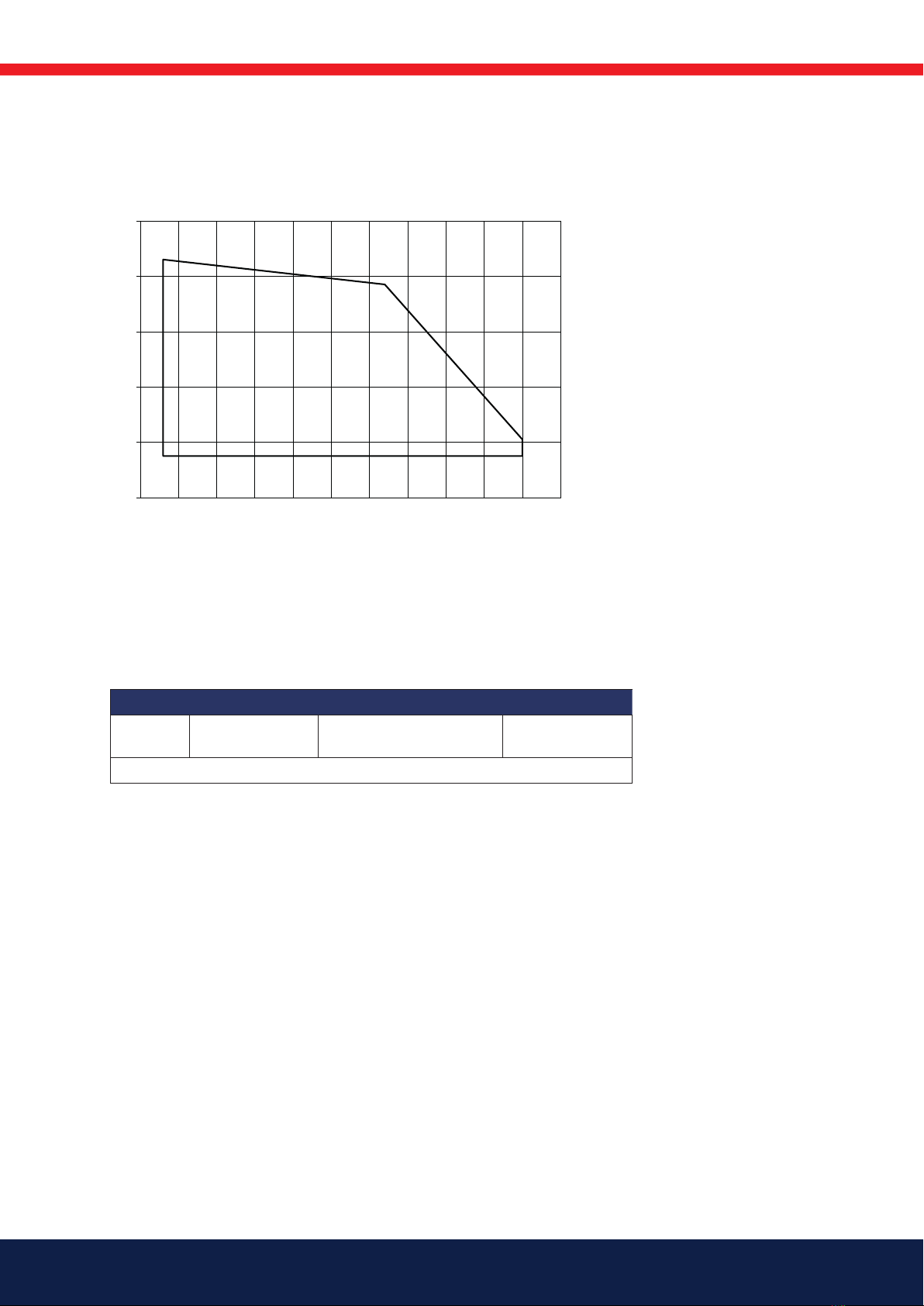
Working eld B 40 MF
2.2 Electric Specication
* Used lower caloric value of 10.00 kWh/kg for
rapeseed oil in accordance with DIN 51605:2010-10
-
1,0
0,0
1,0
2,0
3,0
4,0
50 100 150 200 250 300
mbar
kW
6.5-29.5 kg/h
65-300 kW
160303-224

9Bentone
2.4 Recommended nozzle and pressure
Nozzle: 45° Solid/semisolid
60° Solid/semisolid
80° Solid/semisolid
Pump pressure 10 bar (8-25 bar) depending on pump model
2.5 Burner installation
2.5.1 Hole patten
Make sure the hole pattern on the boiler is designed for burner ange.
Because of the various boiler types with varying furnace geometries and
furnace loads, it is impossible to commit to a certain scattering angle or a
specic distribution pattern.
It should be noted that the scattering angle and distribution pattern changes
with pump pressure.
d1
d2
d3
Combustion device d1d2d3
B 40 MF ø (115) 165 M14 ø 200-250
Burner correspond to IP 20
2.3 Setting of brake plate and air ow
a
b
e
c
d
a b c d e
B 40 MF 2,5-3,0 2,0 6,5-7,0 2,0 5,0
!*NB It is important
that the spark does
not strike against the
brake plate or nozzle
!

10 Bentone
!Altered structure of the oil can give rise to altered viscosity, pumpabilty and ignitability. This can
cause the pump, valves and nozzles to get blocked
2.6 Oil grades
The burner is tested and approved for pure rapeseed oil that complies with
standard DIN 51605:2010-10.
The burner is designed to be able to burn oils with a higher viscosity, both
of biological and fossil origin. The maximum viscosity with which the burner
is tested is 75 mm²/s, 0–130°c. Another way of dening which kind of oil
the burner can handle is that the oil must be of such a nature that it can be
pumped by the burner pump at the temperature the oil has at the point of
access to the pump.
The burner, without the pump, is designed to withstand the more corrosive
environment often created by oils of biological origin.
The Suntec E1069 pump is NOT designed for aggressive oils.
The burner pump has a service life of approx. 3–5 years if the oil is of a grade
that complies with standard DIN 51605:2010-10. If oil of a different grade
is used, especially if the oil contains contaminants such as particles, press
residue, metal swarf etc., or has chemical aggression, the pump may be
expected to have a signicantly shorter service life.
The pump is considered to be a wearing part and is not covered by the
warranty.
Pressure at the pump inlet must be -0.30 to max 2.0 bar. If there is a noise
from the pump, the oil is not pumpable at the current temperature or ow.
A transport oil pump combined with preheater is then needed to supply the
burner’s pump with oil for trouble-free operation.
The oil distribution system must be designed with the required equipment
such as lters, transport oil pump, preheater and reduction valve to provide
trouble -free operation. Max lter size is 120 µm and the oil may need to be
ltered in several steps.
In the case of a standstill in which the oil can be expected to change structure,
for example aging or phase transitions due to temperature and storage, the
burner must be ushed with fuel oil after the standstill. This procedure ensures
a good start after standstill.
Otros manuales para B40 MF
2
Tabla de contenidos
Otros manuales de Equipos industriales de Bentone


