bemodern PRYZM 5D 1000L Guía

1
Instructions for installation
Patent pending
UK Registered Design
R1 Aug 2019 200789_1
Camino- Chimney Breast
Plinth/ No Plinth Options

2
Contents
Technical Specification 3
What is in the Boxes 4 –5
Installation- Introduction 5
Installation- Including Optional Plinth 6
Installation- Excluding Optional Plinth 7
Assembly- Hanging System 8
Assembly- Decorative Panel 9-11
Assembly- Framework 12-13
Assembly- Hearth 13
Assembly- Hearth & Framework 14
Installation- Fixing To The Wall 15-16
Installation- Fixing The Fire 17
Installation- Fitting The Decorative Panels 18
Maintenance / Troubleshooting 19
200789_1

Excluding
Plinth
Including
Plinth
Ceiling
(Without
Coving)
Ceiling (Without Coving)
Floor
3
Technical Specification
200789_1
Fire Description Logs
Dimensions
A B C D E
53” CAMINO
CHIMNEY BREAST
PRYZM 5D 1000L
Timber
Wall mounted:
Excluding Plinth
4 LRG
1220mm 2009mm
290mm 1350mm 212mm
53” CAMINO
CHIMNEY BREAST
PRYZM 5D 1000L
Timber
Floor standing:
Including
Removable
Plinth
4 LRG
1220mm 2253mm
290mm 1350mm 212mm
Note: All dimensions stated above are the minimum requirements for installation in rooms without coving
installed. The chimney breast can be installed in rooms with ceiling heights greater than these dimensions.
For installation excluding the plinth adjust the installation dimensions on Page 7 accordingly and for
installation including the plinth follow the installation dimensions on Page 6.
4
200789_1
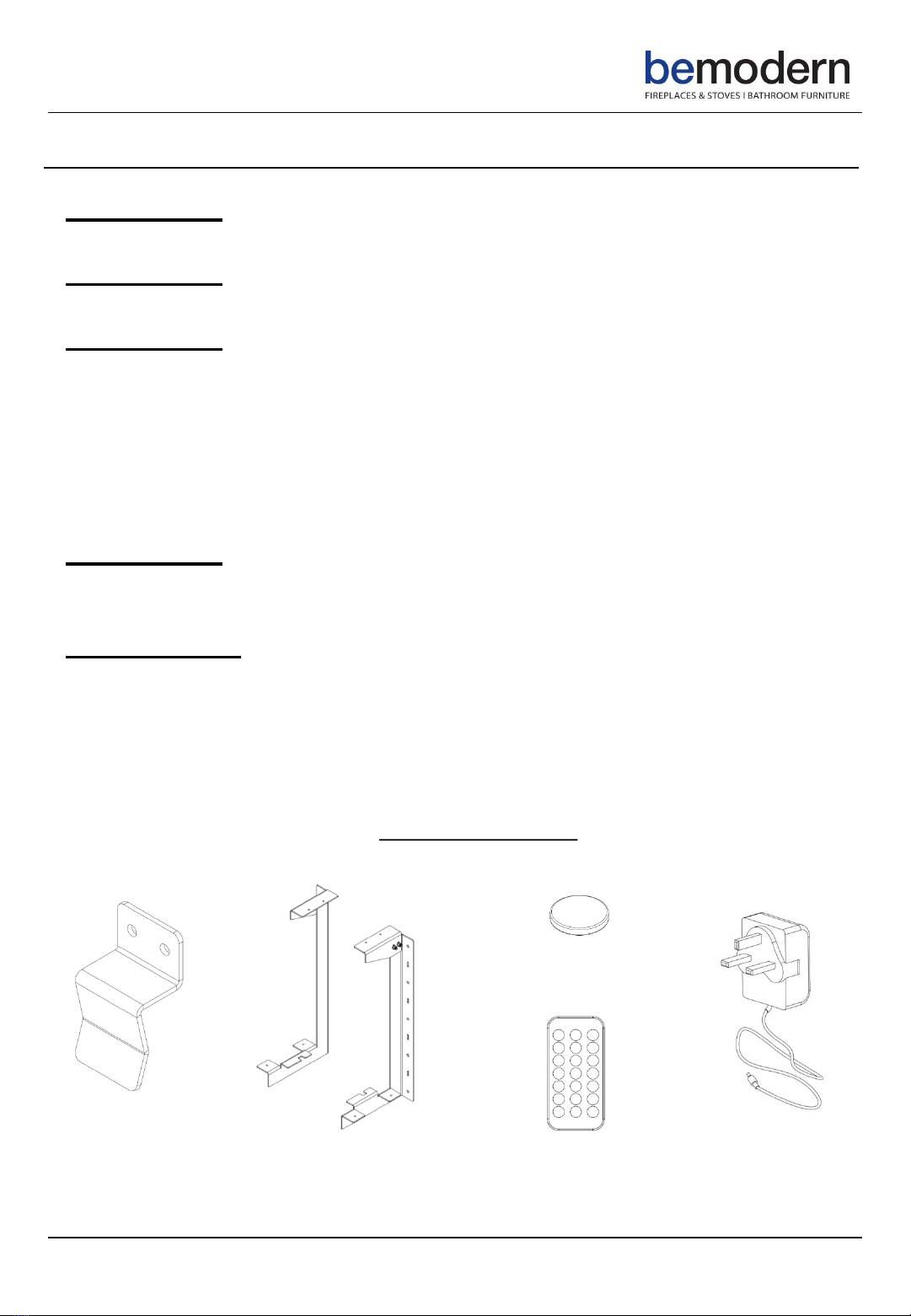
What Is In The Boxes?
4 X
Locating Clips
2 X
Fire Mounting Brackets
Box- 024287 1000L PRYZM Fire Engine x 1, Logs x 4, Fire Remote x1
Box -031658 Optional Plinth x 1
Box- 029920
Component “A” Wall Fixing Panel x 1
Component “B” Light Bleed Cover x 1
Component “C” Large Decorative Panel x 1
Components “D” & “E” Small Decorative Panel x 2
Component “F” Panel Top Fixing Rail x 1
Component “G” Panel Bottom Fixing Rail x 1
Component “H” Heat Deflector x 1
Box- 029890
Components “J” & “K” Assembled Column Front and Sides x 2
BOX –029882
Component “L” Front Top Fixing Rail x 1
Component “M” Rear Fixing Rail x 1
Component “N” Front Bottom Fixing Rail x 1
Component “P” Assembled Floating Hearth with Pre-installed LED Lights x1
Also included in Box 029882 are two smaller boxes with all the hardware (pins and dowels
etc.), the plug and remote for the pre-installed under hearth lighting and the two wall
hanging brackets for hanging the fire. See below and overleaf.
1 X
Remote For Under
Hearth Lighting
1 X
Plug For Under
Hearth Lighting
1 X
CR2025 3V Battery For
Remote
5
200789_1
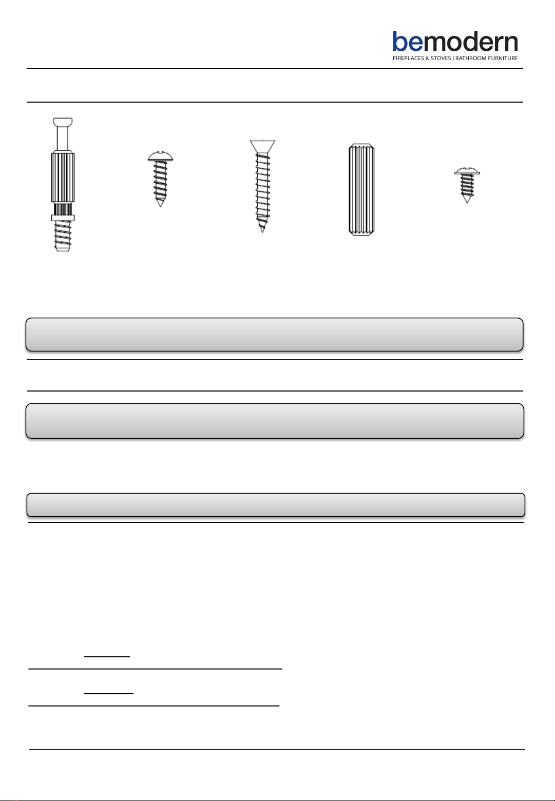
4x
3.5mm X 9.5mm
Pozi Flange Head Screws
12 X
No.8 x 30mm
C/Sunk Screws
30 X
No.8 x15mm
Domed-Head
Screws
18 X
6 x 34mm
Pins
12 X
8 x 30mm
Dowels
What Is In The Boxes Continued…
Installation –Introduction
Note: The chimney breast is a two adult person lift. A second person will be required to lift and
support the chimney breast during installation.
Before the chimney breast can be installed, consideration will need to be given to routing the
power supply to the fire. This will affect the stages of the installation process. We advise a qualified
electrician conduct any electrical parts of the installation.
Note: A double wall socket is required for the operation of the chimney breast.
Unpack your new chimney breast and locate the Wall Fixing Panel- Component “A”- Box 029920.
The Wall Fixing Panel- is to be used so the weight of the components can be distributed across a
larger area and enable the installer to achieve a good solid fix to the wall in various points across
the panel as detailed in the following instructions.
The first step to installation will be the fitment of the Wall Fixing Panel- Component “A”, in the
desired position in the room. The installation procedure will be dependant on the variation of
chimney breast purchased.
Installation including an optional plinth- Minimum ceiling height required is 2300mm.
Follow Diagram 1- Page 6, then continue to Page 8
Installation excluding an optional plinth- Minimum ceiling height required is 2160mm.
Follow Diagram 2- Page 7, then continue to Page 8
Please ensure all fixings are present before commencing installation. If anything is missing please

If fixing into a stud wall, locate the studs and consider positioning the Wall Fixing Panel over as many studs
as possible.
Minimum of 2 studs recommended, as well as the 13 additional fixings points ,as detailed in Diagram 1.
Please note suitable fixings for the wall medium should be used. See important notes Page 15.
200789_1 6
Installation –Including Optional Plinth
Minimum Ceiling Height Required- 2300mm (As shown on Page 3)
Mark a centre line on Wall Fixing Panel- Component “A”-as shown in Diagram 1.
Decide on the installation location of the chimney breast and fix the Wall Fixing Panel using the
recommended dimensions and fixing points, as shown in Diagram 1.
Position the panel on the wall and mark- Position Z, drill and temporarily fix. Ensuring the panel is level and
plumb, mark and drill the additional fixing points. Finally fix into position, depending on the wall medium
it may be necessary to plug the drilled holes. See important notes Page 15.
Note: The accuracy and fixing of this panel is critical to the whole installation process- Ensure the Wall
Fixing Panel- is plumb and level before proceeding further.
Note: All dimensions stated are the minimum requirements for installation including an optional plinth.
Component “A” must be installed from the floor at 265mm, as detailed in Diagram 1, even if the ceiling
height is greater than 2300mm.
Diagram 1
A

If fixing into a stud wall, locate the studs and consider positioning the Wall Fixing Panel over as many studs
as possible.
Minimum of 2 studs recommended, as well as the 13 additional fixings points ,as detailed in Diagram 2.
Please note suitable fixings for the wall medium should be used. See important notes Page 15.
Mark a centre line on Wall Fixing Panel- Component “A”-as shown in Diagram 2.
Decide on the installation location of the chimney breast and fix the Wall Fixing Panel using the
recommended dimensions and fixing points, as shown in Diagram 2.
Position the panel on the wall and mark- Position Z, drill and temporarily fix. Ensuring the panel is level and
plumb, mark and drill the additional fixing points. Finally fix into position, depending on the wall medium
it may be necessary to plug the drilled holes. See important notes Page 15.
Note: The accuracy and fixing of this panel is critical to the whole installation process- Ensure the Wall Fixing
Panel- is plumb and level before proceeding further.
7
200789_1
Installation –Excluding Optional Plinth
Minimum Ceiling Height Required- 2160mm (As shown on Page 3)
Diagram 2
Note: For ceiling heights between 2160mm and 2300mm we recommended following the installation
dimensions, as detailed in Diagram 2. The critical dimension to adhere to is 2040mm. This will ensure an
approx. 50mm gap between the ceiling and the top of the chimney breast is achieved, which is required
for hanging the decorative panels in a later procedure. Alternatively for ceiling heights greater than
2300mm follow the handy table below or adjust the dimensions accordingly.
A
Req. hearth Top
Height (Y-P3)
Installation
Height(X)
Min Ceiling
Height req.
208mm 120mm 2160mm
350mm 262mm 2300mm
400mm 312mm 2350mm
450mm 362mm 2400mm

8
200789_1
Once the Wall Fixing Panel- Component “A” has been secured to the wall, the next step is the
fitting of the fire mounting brackets -Box 029882.
The Wall Fixing Panel comes with pre drilled holes so the brackets can be attached in the correct
position. Attach the brackets, as shown in Diagram 3, using the supplied screws, 9 x No.8 x15mm
Domed-Head screws per bracket.
Ensure the rear of the bracket sits on the top edge of the panel, as shown in Diagram 4.
Once the brackets have been fitted, the light bleed cover- Component “B”- Box 029920 , needs
to be fastened to the top of the fire mounting brackets- align this up tight against the wall and
secure in place with the 2 x No.8 x15mm Domed-Head screws supplied, as shown in Diagram 5.
Diagram 4
B
A
Fire Mounting
Brackets
B
Diagram 5
Diagram 3
Assembly –Hanging System
X 10
Surplus
Cardboard
Note: Before laying the panels down onto a flat surface, make sure the surface is clear of sharp
objects and other debris that may damage the decorative surface. Consider using the surplus
cardboard packaging to help protect the decorative surface- as shown in Diagram 6.
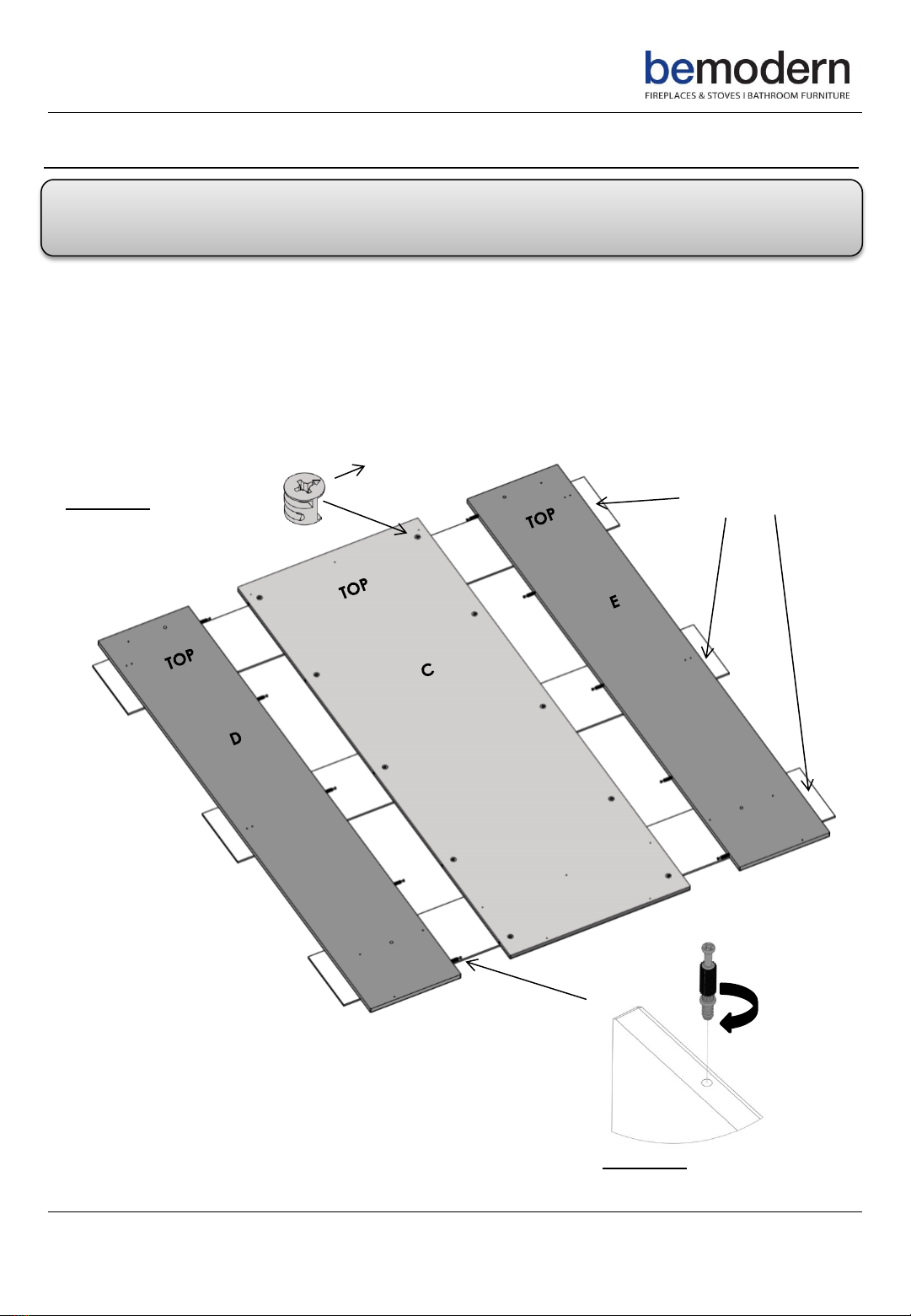
Locate Component “C”-Box 029920 and position this panel face down. The 10 x Cams have
been pre-installed. Please check that the arrows on the cams are pointing to the outer edge of
the panel to allow the pin to locate correctly.
Locate Components “D” and “E”- Box 029920, screw the pins into the relevant sides of the
panels, 5 X Pins per side, as shown in Diagram 7.
Then position Components “D” and “E” face down either side of Component “C”- as shown in
Diagram 6.
9
200789_1
Assembly –Decorative Panel
Diagram 6
X10
Diagram 7

Diagram 9
X 10
10200789_1
Assembly –Decorative Panel Continued…
Push both Components “D” and “E” into Component “C” ensuring the back surfaces are level
and the ends are flush as shown in Diagram 8. Once in position, lock together by turning the
cams ½ turn clockwise, this will lock the pins into the cams, as shown in Diagram 9.
Once Components “C”, “D” and “E have been locked together, the 4 x locating clips need to
be attached to the sides of Components “D” and “E” as shown in Diagram 10. The holes have
been pre-drilled for ease of assembly. Make sure the locating clips are fixed square to the edge.
Diagram 8
Diagram 10
Position the 4 x locating clips
and align with the screw holes
and screw in place using the
8 x No.8 x15mm Domed-Head
screws provided .
Tabla de contenidos
Manuales populares de Accesorios para chimeneas de otras marcas


Bronpi
Bronpi KIT-1 Manual de usuario

Town & Country Fireplaces
Town & Country Fireplaces 22150051 Manual de usuario

Travis Industries
Travis Industries 33 DVI Manual de usuario

Superior
Superior ASD3628-TI Manual de usuario

pleasant hearth
pleasant hearth OFP28WG Manual de usuario

IHP
IHP Astria Series Manual de usuario


