6640-888 9/05 ©
A Division of KW AUTOMOTIVE North America, Inc.
3
16. Using a die grinder with a cutoff wheel, or suitable tool, cut out the section of the frame rail marked by
the transferred locations from the template. CAUTION: Be aware of the fuel, brake and electrical
components inside the frame rail when cutting through the frame, so as not to cause damage to these
components. CAUTION: Always wear eye protection when using power tools.
17. Remove the two rivets that exist in the lower frame rail just forward and aft of the removed frame
section by grinding slots in the rivet heads using a die grinder with a cutoff wheel, or suitable tool.
Remove the heads of the rivets with an air chisel, or suitable tool. Drive the remaining rivet shanks
through the frame rail with an air chisel or suitable tool. CAUTION: Do not grind through the rivet
heads into the lower flange of the frame rail; also, be aware of the fuel, brake, and electrical
components inside the frame rail when driving the rivets through the frame. CAUTION: Always
wear eye protection when using power tools.
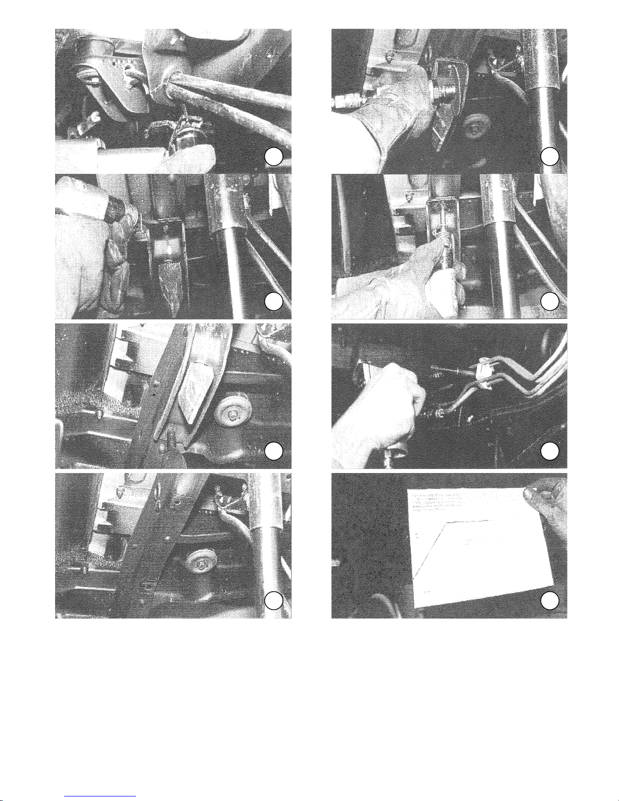
18. Trim the frame cross member that intersects the frame rail cutout to a height that is parallel with the
bottom of the frame rail cutout. (PHOTO 22) The middle aft section of this frame cross member must
be trimmed up to the top of the frame cross member so that the rear axle housing has clearance upon
full suspension compression. (PHOTO 23) CAUTION: Always wear eye protection when using
power tools.
19. The rear axle housing vent hose must be relocated and the original mounting strap trimmed off to
insure rear axle housing clearance during suspension compression. Remove the bolt that secures the
rear axle-housing vent to mount. (PHOTO 24) Open the vent tube clamp enough so that it can be
moved on the vent tube. Relocate the vent tube clamp to the existing hole in the fuel tank forward
cross member. (PHOTO 25) Install the kit-supplied hardware and torque to 15 Ft.-lbs. Trim off the vent
tube mount forward of the brake hose union. (PHOT 26) CAUTION: Always wear eye protection
when using power tools. Exercise caution when cutting near brake system components so that
damage does not disable the brake system.
20. Trim the front middle edge of the fuel tank retaining cross member directly behind the rear axle
housing approximately 7” wide and 1” deep so that the rear axle housing rear cover has sufficient
clearance upon full suspension compression. (PHOTO 27) NOTE: There is an electrical system
harness that lies on top of the cross member, remove the bolt and clip that retain this electrical
harness before any trimming is accomplished. After the trimming operation, replace the harness and
securing hardware. CAUTION: Always wear eye protection when using power tools.
21. Open up the underbody cross member directly over the center of the drive shaft by locating the kit
supplied template on the cross member and marking the cross member according to template
instructions. Cut out the marked section of the underbody cross member. (PHOTO 28 & 29)
CAUTION: Always wear eye protection when using power tools.
22. Position the kit supplied frame reinforcement on the frame, aligning the small hole in the reinforcement
with the vacant bolthole in the chassis rail. Clamp the reinforcement in place using c-clamps or a
suitable tool.
23. Using the frame reinforcement as a guide, drill through the frame rail at the 4 forward and 4 aft, and ½
“holes in the reinforcement using a ½” drill bit. (PHOTO 30) CAUTION: Be aware of the fuel, brake and
electrical components inside the frame rail as the frame is being drilled. CAUTION: Always wear eye
protection when using power tools. NOTE: The drilling operation can be eased by starting off with
a smaller “pilot” drill bit and working up gradually in drill bit size to this final drill bit size.
24. De-burr the drilled holes in the frame rail and install the kit supplied ½” hardware. Torque the hardware
to 100-120 Ft.-lbs. After the bolts that secure the frame reinforcement to the side of the chassis are
torqued, drill through the forward and aft holes in the bottom of the frame reinforcement and install the