BCS SD03 speed dome 66 Manual de usuario

Speed Dome 66 Installation Manual

2
Table of Contents
1INSTALLATION...................................................................................................6
1.1 Installation Preparation .........................................................................................................................6
1.2 Installation Mode....................................................................................................................................6
1.2.1 Speed Dome Installation Mode.......................................................................................................6
1.2.2 Bracket Installation Mode................................................................................................................7
2SPEED DOME INSTALLATION..........................................................................9
2.1 General Introduction..............................................................................................................................9
2.2 Hanging Bracket Speed Dome Installation........................................................................................9
2.2.1 Installation Requirement..................................................................................................................9
2.2.2 Hanging Bracket Installation ...........................................................................................................9
2.2.3 Camera Installation.........................................................................................................................11
2.3 Corner Bracket Speed Dome Installation.........................................................................................13
2.3.1 Installation Requirement................................................................................................................13
2.3.2 Corner Bracket and Hanging Bracket Installation......................................................................13
2.4 Pole Bracket Speed Dome Installation.............................................................................................15
2.4.1 Installation Requirement................................................................................................................15
2.4.2 Pole Bracket Installation ................................................................................................................16
2.5 Suspended Bracket Speed Dome Installation.................................................................................17
2.5.1 Installation Requirement................................................................................................................17
2.5.2 Accessories Installation .................................................................................................................17

3
Welcome
Thank you for purchasing our speed dome!
Please read the following safeguards and warnings carefully before you install
or use the product!

4
Important Safeguards and Warnings
Safety Measures
Qualified Engineer Needed
zThe installation engineer or maintenance engineer shall have corresponding
CCTV system installation certificate or maintenance qualification certificate.
zThe installation engineer or maintenance engineer shall have qualification
certificate for work at height.
zThe installation engineer or maintenance engineer shall have the basic
knowledge and operation technique for low-voltage cable layout and low-voltage
electronic cable connection.
zPlease read the installation manual carefully and keep it well for future reference,
zWe are not liable for any problems caused by unauthorized modifications or
attempted repair.
Lifting Appliance Requirement
zPlease select the proper speed dome installation mode and use the lifting
appliances at the safety environment.
zThe lifting appliances shall have the enough capacity to reach the installation
height.
zThe lifting appliances shall have safe performance.
Precautions
Safety Transportation
zHeavy stress, violent vibration or water splash are not allowed during
transportation, storage and installation.
zThis series product must use split type package during the transportation.
zWe are not liable for any damage or problem result from the integrated package
during the transportation.
When device is malfunction
Shut down the device and disconnect the power cable immediately if there is smoke,
abnormal smell or abnormal function. Please contact your local retailer ASAP.

5
Do not try to dismantle or modify the device
zThere is risk of personal injury or device damage resulting from opening the shell.
zPlease contact your local retailer if there is internal setup or maintenance
requirement.
zWe are not liable for any problems caused by unauthorized modifications or
attempted repair.
Do not allow other object falling into the device
zPlease make sure there is no metal or inflammable, explosive substance in the
speed dome.
zThe above mentioned objects in the device may result in fire, short-circuit or
damage.
zPlease shut down the device and disconnect the power cable if there is water or
liquid falling into the camera. Please contact your local retailer ASAP.
zPlease pay attention to the camera. Avoid the sea water or rain to erode the
camera.
Handle carefully
Do not allow this series product fall down to the ground.
Avoid heavy vibration.
Installation Environment Requirement
zThis series speed dome should be installed in a cool, dry place away from direct
sunlight, inflammable, explosive substances and etc.
zThis series product shall be away from the strong electromagnetism radiant,
please keep it away from wireless power, TV transmitter, transformer and etc.
Daily Maintenance
zPlease use the soft cloth to clean dust on the shell, or you can use soft cloth with
cleaning liquid to clean the shell and then use soft cloth to make it dry.
zDo not use gasoline, dope thinner or other chemical material to clean the shell. It
may result in shell transfiguration or paint flake.
zDo not allow the plastic or rubber material to touch the shell for a long time. It
may result in paint flake.

6
1INSTALLATION
1.1 Installation Preparation
Basic Requirement
zAll installation and operation here should conform to your local electrical safety
codes.
zBefore installation, please open the package and check all the components are
included. Please make sure the speed dome installation environment and
installation mode can meet your requirement. If there is special requirement,
please contact your local retailer for more information.
zWe assume no liability or responsibility for all the fires or electrical shock caused
by improper handling or installation.
Check installation space and installation location intension
Please make sure the installation environment has enough space to install the speed
dome and its corresponding bracket.
Please make sure the ceiling, wall, bracket can support the speed dome and its
corresponding installation component. The safety factor shall be 4X.
About cable
Please select the cable according to your transmission distance.
The minimum video coaxial-cable requirement is:
z75 ohm.
zFull cable with copper conductor
z95% knitted copper shield
International Model Max Distance
(Ft\M)
RG59/U 750ft (229m)
RG6/U 1,000ft (305m)
RG11/U 1,500ft (457m)
Set dial switch button
Set dial switch button according to control protocol and speed dome address.
(Please refer to user’s manual for detailed information.)
Please keep all package material well for future use
Please keep speed dome package material well in case you need to send it back to
your local retailer or manufacturer for maintenance work.
Non-original package material may result in device damage during the transportation.
1.2 Installation Mode
1.2.1 Speed Dome Installation Mode
The integrated speed dome has the following installation modes:

zEmbedded installation
zIn-ceiling installation
zBracket installation
1.2.2 Bracket Installation Mode
The bracket installation consists of the following modes:
zHanging installation
zCorner installation
zPole installation
zSuspended installation
The bracket installation is suitable for indoor and outdoor environment. The outdoor
speed dome has a sun-shade cover and it also has an internal heater device.
The outdoor speed dome IP standard is IP 66.
1.2.2.1 Hanging Installation
This series installation mode is suitable for indoor and outdoor hard wall structure.
See Figure 1-1. Please refer to chapter 2.2 for detailed information.
Figure 1-1
1.2.2.2 Corner Installation
The corner installation is suitable for indoor and outdoor hard wall structure
environment where the angel is 90 degrees. See Figure 1-2. Please refer to chapter
2.3 for detailed information.
7

Figure 1-2
1.2.2.3 Pole Installation
Pole installation is suitable for indoor and outdoor hard pole structure. See Figure
1-3. Please refer to chapter 2.4 for detailed information.
8
Figure 1-3
1.2.2.4 Suspended Installation
The suspended installation has the following two types. Please refer to chapter 2.5
for detailed information. See Figure 1-4.
With Pole Without Pole
Figure 1-4
2SPEED DOME INSTALLATION
2.1 General Introduction
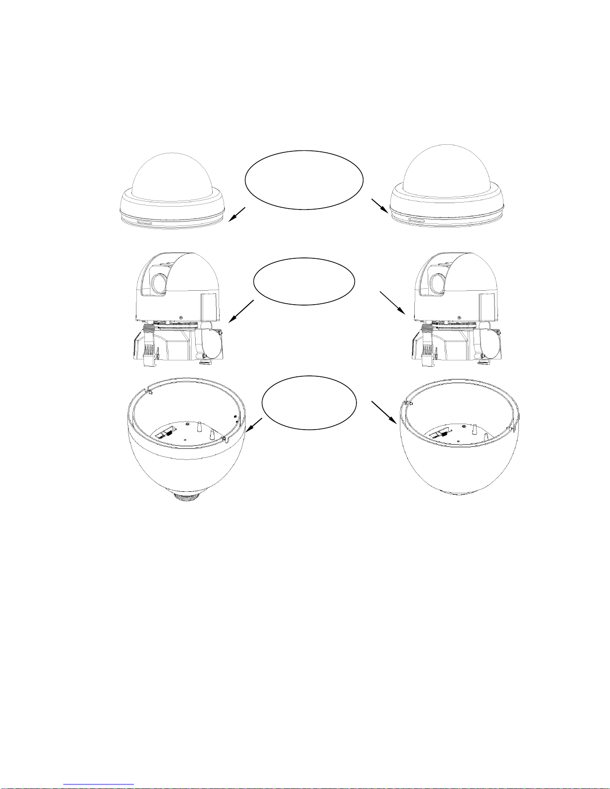
Speed dome consists of the following components. See Figure 2-1.
Speed Dome Cover
Component
Body Component
External Cover
Component
Figure 2-1
2.2 Hanging Bracket Speed Dome Installation
2.2.1 Installation Requirement
The hanging bracket is suitable for indoor or outdoor hard wall structure.
The wall thickness shall support the expansion bolt.
The wall shall support the 4x speed dome weight.
2.2.2 Hanging Bracket Installation
Draw the hole position in the wall in accordance with the hanging bracket bottom
installation pole. Then dig holes. Please refer to Figure 2-2.
9

Figure 2-2
You can use socket head cap screw to fix hanging bracket and external cover
component. (Please install waterproof sealing cushion)
10
M5×12 socket head cap screw
Hanging Bracket
External Cover Component
Figure 2-3
After you installed bracket and external cover components, loosen captive screws
and open the panel. Draw the power cable through the hanging bracket and then fix
the bracket in the wall. Please pay attention to the waterproof between the bracket
and then wall. See Figure 2-4.
Power Cable
Captive Screws
Tabla de contenidos
Otros manuales de Cámara de seguridad de BCS


