BCDVideo BCD-RGD-804P-MT Manual de usuario
1
+1 847. 205.1922
info@bcdvideo.com
www.bcdvideo.com
BCD214-RGD-804P-MT
USER GUIDE

BCD-RGD-804P-MT
2www.bcdvideo.com
table of contents
1 WEB Configuration 3
1.1 Preparing and Entry 3
1.1.1 Switch Default Configuration 3
1.1.2 Computer basic configuration requirement 3
1.1.3 Establish network connection 3
1.1.4 Check network weather connect between computer and switch 4
1.1.5 Login switch management interface 4
1.2 Web management interface 5
1.2.1 Basic information 5
1.2.2 Configuration 7
5.2.3 Monitor(Status Display) 60
5.2.4 Diagnostics 89
5.2.5 Maintenance 91
2Command Line Management 93
2.1 Configure HyperTerminal 93
2.1.1 USB 115200-8-N-1 port connect with Device console port 93
2.2 Login equipment and basic command Query 95
2.2.1 System Information Query 95
2.2.2 Recovery factory default 95
2.2.3 Logout 96
2.2.4 Query / ModifyIP 96
2.2.5 Using own command help function 96
3Technical Parameters 97

BCD-RGD-804P-MT
3
1 WEB configuration
1.1 Preparing and Entry
Configure the switch through Web pages, this chapter will take you through the equipment configuration process.
Aer completing the hardware installation, you need to ensure that the computer networks parameters to meet certain
conditions before accessing the Settings page.
1.1.1 Switch Default Configuration
The system default IP address is: 192.168.0.240, user name: admin; password: admin
1.1.2 Computer basic configuration requirement
Ethernet card installed, you can access the Internet through a network port. we recommend using a Computer (or better),
minimum display resolution support 1024 * 768 pixels for better view.
1.1.3 Establish network connection
Open network parameter configuration of Computer shown as below. Select the Internet Protocol (TCP / IP), enter the
Internet Protocol (TCP / IP) Properties window. Select the input IP address in addition to the default IP address and subnet
mask (255.255.255.0), click on the OK button to complete the operation.
(Note: The IP address and switch must be in the same subnet.)

BCD-RGD-804P-MT
4www.bcdvideo.com
1.1.4 Check network whether connect between computer and switch
Use the ping command of Operating System, enter switch’s IP address, if reply normally, then network connectivity;
otherwise, check the network connection.
1.1.5 Login switch management interface
Running the browser, enter the switch default IP address (192.168.0.240) in address column, click Enter. Login dialog box,
as shown below, enter your user name and password (the default user name: admin, password: admin), click the OK
button or directly enter into the system configuration page. Aer a successful login interface as follows:
BCD-RGD-804P-MT
5
1.2 Web Management Interface
1.2.1 Basic information
Switch Configuration page is divided into Configuration, Manager, Diagnostics, Maintenance of four parts. As below:
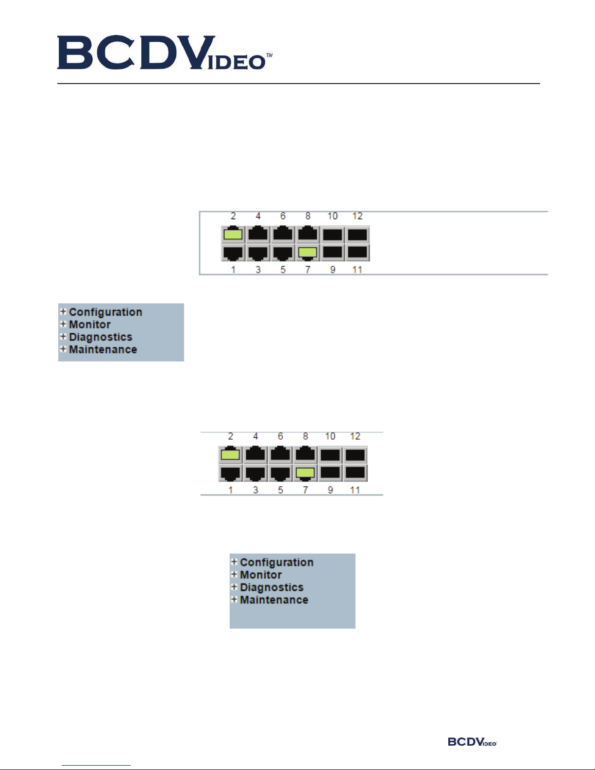
Port State Overview. This area displays the current status of the device connection port. When the indicator is green
indicates that the corresponding port is connected, the indicator is gray, indicating the port not connected or enabled,
as shown below:
Navigation column: Click on a navigation column entry, the user can make the appropriate feature set and view,
as shown below:

BCD-RGD-804P-MT
6www.bcdvideo.com
Configuration: Click the navigation column Configuration option, the system
will expand to show the relevant configuration interface, users can set the inter-
face-related functions.
Monitor: Click on the navigation column
Monitor option, the system will expand
to show the relevant status interface,
user-related functions can be provided in
the interface.
Diagnostics: Click on the navigation column Diagnostics option, the system
will expand the relevant components for switch device detection.
Maintenance: Click on the navigation column Maintenance option, the
system will be displayed in the management area related to user management
interface related functions can be provided in the interface.

BCD-RGD-804P-MT
7
1.2.2 Configuration
1.2.2.1 System
A. System Information
Enter [System]→[Information] navigation column, enter the system contact, system name, system location, time zone
oset system aer setting, click [Save] button to complete the basic configuration information.
Click [Reset] button, return to the data before system [Save]
Interface items introduction:
Interface items Configuration Introduction Factory configuration
System Contact 0~255 characters Equipment maintenance personal
contact information
No
System Name 0~255 characters Switch name, is used to specify
switch function (The first must be
a letter, the last one cannot be a
special sign)
No
System Location 0~255 characters Describing the location information
of device, such as production line 1
System Time zone Oset -720~720,unit:min oset between equipment time zone
and system time zone
0

BCD-RGD-804P-MT
8www.bcdvideo.com
B. IP Address Configuration
Enter → [IP] navigation column, the page used to configure the address of the device management. The current status ad-
dress of the device, a mask, router will be displayed in the form. Aer modifying the contents of the form, click [Save] button
to complete the address modification or click [Reset], it will be restored to the original value form content unmodified.
Router is optional item, default is empty. Set relevant parameters, click [Save] button to complete the configuration.
IP interface: Interface items introduction (May dierent VLAN set dierent IP addresses, to meet the dierent hosts in
VLAN access to the switch).
Interface items Configuration Introduction Factory setting
Delete Select / not selected Select this option to delete an existing IP interface. not selected
VLAN 1~4095 number The VLAN associated with the IP interface. Only ports
in this VLAN will be able to access the IP interface. This
field is only available for input when creating an new
interface.
No
DHCP Select / not selected Enable the DHCP client by checking this box. If this
option isenabled, the system will configure the IP
address and mask of the interface using the DHCP
protocol.
not selected
Address Switch IP address The IPv4 address of the interface in dotted decimal
notation.
192.168.0.240
Mask Length 1-30 The destination IP network or host mask, in number of
bits (prefix length).
24
Add Interface Add an IP address settings
BCD-RGD-804P-MT
9
Click “Add Interface” Add a new IP interface.
IP router = Interface items introduction:
Click “Add Router” to add a new IP route interface.
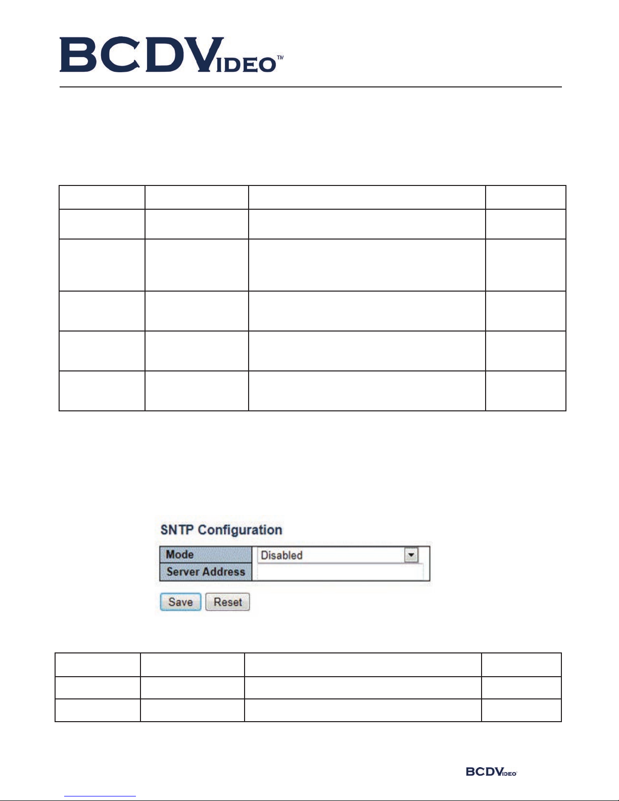
C. SNTP Time Server Configuration
Enter [System] → [SNTP] Navigation, Time server configuration page, can be turned on when the remote NTP server,
and configure remote SNTP time server, click [Save] button to complete time server configuration.
Interface items introduction:
Interface items Configuration Introduction Factory Setting
Delete Select / not selected Select this option to delete an existing IP route. not selected
Network IP address The destination IP network or host address of this
route. Valid format is dotted decimal notation or a
valid IPv6 notation. A default route can use the value
0.0.0.0 or IPv6 :: notation.
NO
Mask Length 1-32 The destination IP network or host mask, in number of
bits (prefix length). It defines how much of a network
address
not selected
that must match,
in order to qualify
for this route.
24 The IPv4 address of the interface in dotted decimal
notation.
192.168.0.240
Gateway IP The IP address of the IP gateway. No
Interface items Configuration Introduction Factory Setting
Mode Disable/Enable Indicates the NTP mode operation. Disable
Server Address Time server IP address Provide the IPv4 or IPv6 address of a NTP server. No

BCD-RGD-804P-MT
10 www.bcdvideo.com
D. Log Server Configuration
Enter [System] → [Log] navigation column, log configuration page, you can configure a remote logging server information,
the device logs information [Save] to a remote server, providing backup viewing. Select the server mode, set the server
address, select the log level, click [Save] button to complete the system logging configuration.
Interface items introduction:
Interface items Configuration Introduction Factory setting
Server Mode Disable/Enable Indicates the server mode operation. No
When the mode operation is
enabled, the syslog message will
send out to syslog server.
Disable Switch name, is used to specify switch function
(The first must be a letter, the last one cannot be
a special sign)
No
Server Address Log configuration
IP address
Configure log server IP address No
5.2.2.2 Ports
Enter the [Ports] navigation column, you can view the connection status of each port, including: link connection, speed,
flow control and maximum frame size and other information, No 1-6 for the front panel port 100M / 1000M RJ45 ports, No
7-8 port for the data connection port, No 9-10 port Gigabit optical interfaces. Link status indication red indicates that the
link down state; green indicates that the link up state.
Port rate mode:
Ports can be selected as “Auto”, “Disabled”, “10mbps HDX”, “10mbps FDX”, “100Mpbs HDX”, “100Mpbs FDX”, “1Gbps FDX”;
This option may be set directly: Auto can automatic identification access type.
Flow Control: enable the port flow control, implement port flow control
The maximum frame size that can be configured port maximum transmission unit, the default is 9600. Select the relevant
parameters, click [Save] button to complete the port configuration. Also Click [Save] button to save changes. Click [Reset]to
cancel any changes made locally and return to previously saved values.
Otros manuales para BCD-RGD-804P-MT
1
Tabla de contenidos
Manuales populares de Enrutador de red de otras marcas


NETGEAR
NETGEAR FS526T - Switch Manual de usuario

Korenix
Korenix JetNet 5710G Series Manual de usuario

Automated Logic
Automated Logic ZN551 Manual del propietario

Cisco
Cisco ASR 1000 Series Manual del operador

EnGenius
EnGenius ESR-9710 Manual de usuario

Cisco
Cisco 805 Series Instrucciones de funcionamiento y seguridad