BAYweb BW-WT1 Manual de usuario

Owner's Manual
[ S/N LABEL HERE ]
Document # BW-WT4-1DOC

BAYweb T ermostat Model BW-WT1 Owner's Manual
Copyrig t © 2009-2010 Bay Controls, LLC
Part Number: BW-WT4-1DOC
Revision: 1.1 November 5, 2010
BAYweb is a registered trademark of Bay Controls, LLC.
Patent pending tec nologies are used in t e BAYweb T ermostat.

Table of Contents
Introduction.............................................................................................................1
About T is Manual..................................................................................................1
Safety Precautions..............................................................................................1
Limited Warranty.................................................................................................3
Limitation on Liability..........................................................................................3
Unaut orized Repair...........................................................................................3
Installation...............................................................................................................4
Overview.............................................................................................................4
Identify Wiring.....................................................................................................6
Install Control Module.........................................................................................7
Install T ermostat Keypad................................................................................10
Test Operation..................................................................................................12
Connect to t e Internet.....................................................................................13
Operation..............................................................................................................14
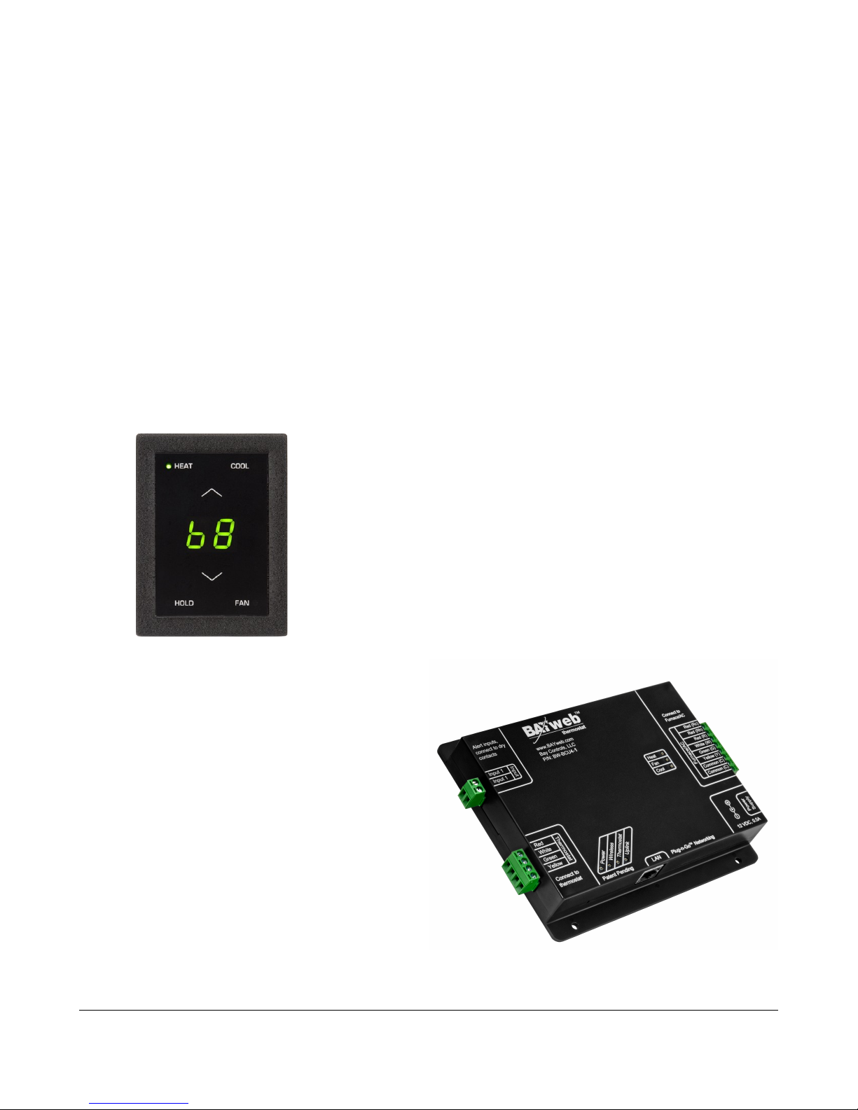
Using t e T ermostat Keypad..........................................................................14
Using t e Web Portal........................................................................................15
Using Your Mobile P one.................................................................................15
Occupancy Sensing..........................................................................................15
Implementing Occupancy Sensing...............................................................15
Testing Occupancy Sensing.........................................................................16
Occupancy Sensing wit Multiple T ermostats...........................................16
Alerting..............................................................................................................17
Implementing Alerting...................................................................................17
Testing Alerting.............................................................................................17
Reference..............................................................................................................18
T ermostat Keypad..........................................................................................18
Error Codes..................................................................................................18
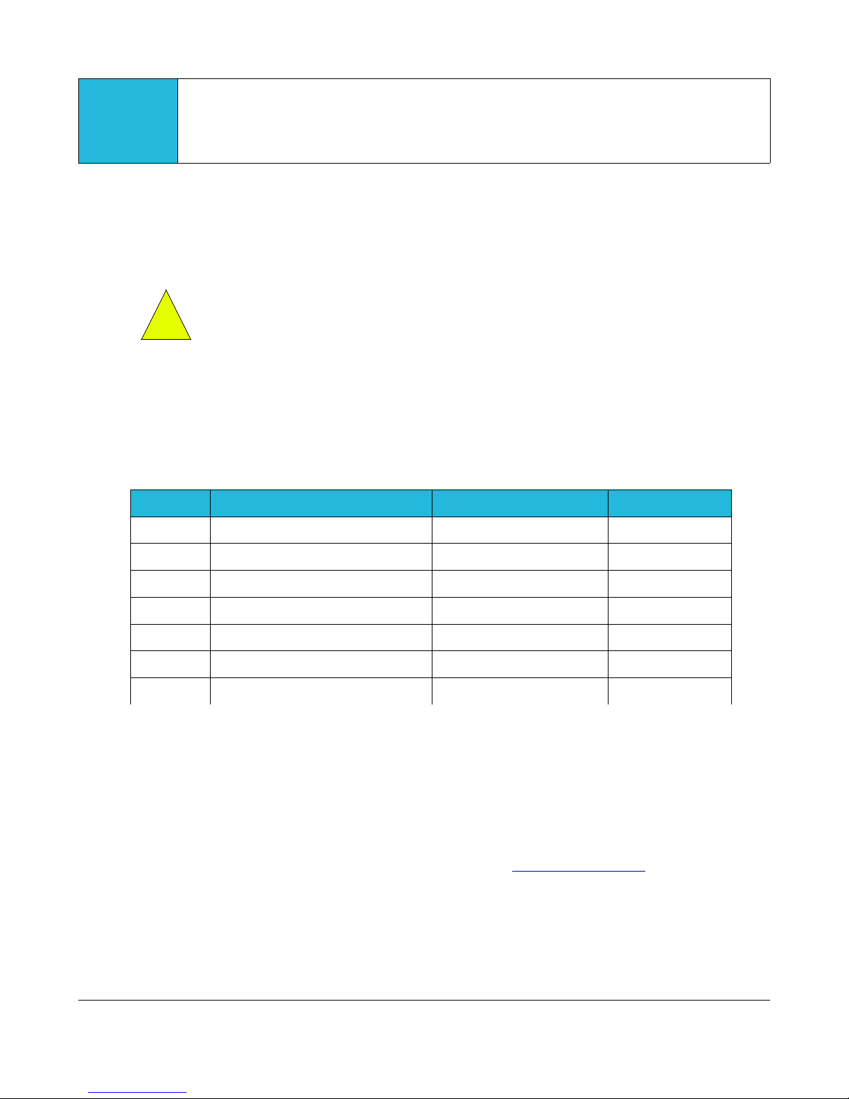
Control Module.................................................................................................19
Alert Input.....................................................................................................19
T ermostat Connector..................................................................................20
Furnace/AC Connector.................................................................................20
LAN Port.......................................................................................................20
Power Supply...............................................................................................20
Status Indicators...........................................................................................20
Troubles ooting................................................................................................21
Solutions to Problems..................................................................................21
Emergency Operation..................................................................................24
Obtaining Support........................................................................................25
T ermostat Connections..................................................................................25
T ermostat Wiring............................................................................................25
Specifications........................................................................................................26


Introduction
T ank you for purc asing t e BAYweb T ermostat. You now ave one of t e most advanced
Heating, Ventilating, and Air Conditioning (HVAC) control systems available today.
T is t ermostat is easily installed by ome owners or HVAC professionals. It can be used to
replace an existing t ermostat or for installation wit new eating or cooling equipment.
T is model of t e BAYweb T ermostat (BW-WT1) is designed for use wit eating and
cooling equipment t at utilize single stage control, w ic is t e most common.
Multistage furnaces are often controlled using single stage t ermostats, andling t e second
stage control internally. If your t ermostat uses 5 wires or less, it is likely using single stage
control. Step 1 of t e installation will verify t at you are using t e correct model of t ermostat
for your equipment.
About This Manual
T is manual contains t e information necessary for installing and operating t e BAYweb
T ermostat. However, since installations may vary, t ese instructions may not cover all details
or variations in t e equipment supplied or every question t at may possibly arise during use.
If a question or situation develops w ic is not answered directly in t is manual, contact
BAYweb support for specific answers and advice.
You s ould become familiar wit t e contents of t is manual before t e t ermostat is put into
service. T is is particularly important wit regard to t e safety precautions listed in t e
Introduction section, and t ose included at relevant points in ot er sections of t is manual.
Note t at t is manual is for t e standard model t ermostat (part number BW-WT1) wit t e
2nd generation control module (part number BW-BCU4-1). t is manual is updated periodically.
You can download t e latest version at www.bayweb.com.
CAUTION: Read, be sure to clearly understand, and t en carefully follow all of t e
directions and procedures included in t is manual. Failure to ad ere to t e
guidelines and specific instructions provided could cause equipment damage and
serious personal injury or deat .
Safety Precautions
Low voltage t ermostats, including t e BAYweb T ermostat, use 24 VAC control signals
limited to 3.2 amperes to interface to your furnace and air conditioning equipment. T ese low
voltage control signals do not normally represent an electric s ock azard unless used in an
environment for w ic t e equipment was not designed for, suc as a wet location.
1
!

Bay Controls, LLC. expressly disclaims responsibility or liability for any injury or damage
caused by failure to observe specified or ot er common safety precautions or failure to
exercise ordinary caution, common sense, and due care required in installing and operating
t e t ermostat even t oug not specified erein.
T e alert message s own ere appears t roug out t is manual to indicate t ose situations
and times w en special care is necessary to prevent equipment damage or personal injury.
CAUTION: T is indicates t at t ere could be t e possibility of equipment damage
or personal injury.
CAUTION: If t is equipment is used in a manner not specified by Bay Controls,
LLC., t ere may be a risk of equipment damage, serious personal injury, or deat .
2
!
!

Limited Warranty
Subject to t e limitations contained below, and except as ot erwise expressly provided
erein, Seller warrants to t e Buyer t at all tangible articles supplied by Seller or services
provided by Seller will be free of defects in materials or workmans ip under normal use and
care until t e expiration of t e applicable warranty period. Goods are warranted for five (5)
years from t e date of purc ase. If Buyer discovers any defects and notifies Seller t ereof in
writing during t e applicable warranty period, Seller s all at its option promptly correct, repair,
or replace F.O.B. point of manufacture t at portion of t e good found by Seller to be defective,
or refund t e purc ase price of t e defective portion of t e goods/services. All replacements
or repairs necessitated by inadequate maintenance, normal wear and usage, unsuitable
power sources, unsuitable environmental conditions, accident, misuse, improper installation,
modification, repair, storage or andling, or any ot er cause not t e fault of Seller are not
covered by t is limited warranty, and s all be at Buyer’s expense. Seller s all not be obligated
to pay any costs or c arges incurred by Buyer except as may be agreed upon in writing in
advance by an aut orized Seller representative. Goods repaired and parts replaced during
t e warranty period s all be in warranty for t e remainder of t e original warranty period or
ninety (90) days, w ic ever is longer.
THERE ARE NO REPRESENTATIONS OR WARRANTIES OF ANY KIND, EXPRESS OR
IMPLIED, AS TO MERCHANTABILITY, FITNESS FOR PARTICULAR PURPOSE, OR ANY
OTHER MATTER WITH RESPECT TO ANY GOODS OR SERVICES.
Limitation on Liability
THE SOLE AND EXCLUSIVE REMEDY FOR BREACH OF WARRANTY HEREUNDER
SHALL BE LIMITED TO REPAIR, CORRECTION, REPLACEMENT OR REFUND OF
PURCHASE PRICE AS PROVIDED UNDER THE FOREGOING LIMITED WARRANTY.
IN NO EVENT, REGARDLESS OF THE FORM OF THE CLAIM OR CAUSE OF ACTION
(WHETHER BASED IN CONTRACT, INFRINGEMENT, NEGLIGENCE, STRICT LIABILITY,
TORT OR OTHERWISE), SHALL SELLER’S LIABILITY TO BUYER AND/OR ITS
CUSTOMERS EXCEED THE PRICE TO THE BUYER OF THE SPECIFIC GOODS
SUPPLIED OR SERVICES PROVIDED BY SELLER GIVING RISE TO THE CLAIM OR
CAUSE OF ACTION.
BUYER AGREES THAT IN NO EVENT SHALL SELLER’S LIABILITY TO BUYER AND/OR
ITS CUSTOMERS INCLUDE “CONSEQUENTIAL DAMAGES”. FOR THIS PURPOSE,
“CONSEQUENTIAL DAMAGES” SHALL INCLUDE, BUT NOT BE LIMITED TO, LOSS OF
ANTICIPATED PROFITS, LOSS OF USE, LOSS OF REVENUE AND LOSS OF CAPITAL.
Unauthorized Repair
In t e event t at t e owner allows t e Web T ermostat to be serviced or repaired by
unaut orized personnel, t e coverage of t e original warranty policy will be automatically
terminated.
3
Installation
Overview
Installing t e t ermostat is a relatively simple process and typically takes from 10 to 30
minutes to complete. You s ould consider t e current outdoor temperature. If unexpected
problems occur, you do not want to risk freezing or cooking someone or somet ing w ile you
are sorting t e problem out.
You will need screwdrivers, a wire stripper/cutter, and a drill for installing t e wall anc ors to
complete t e installation. A volt/o m meter can be elpful for troubles ooting but not required.
Most conventional t ermostats, probably including t e one you are replacing, use a single
wall mounted enclosure. T e BAYweb t ermostat uses two modules: t e T ermostat Keypad
and t e Control Module. T is design eliminates t e use of batteries and potential need to pull
new wire out to t e wall, and results in a more compact and elegant design.
T e T ermostat Keypad is mounted on wall in place of
your existing t ermostat.
If your existing t ermostat is larger t an t e new one,
you can easily pull off t e keypad later to touc up t e
paint after you ave completed t e installation.
T e control module mounts near or on your
furnace and/or air conditioner, and is spliced
into your existing t ermostat wire.
T e module can be powered directly from t e
furnace or from an outlet ideally on t e same
circuit as your furnace.
You will need an Internet connection for t e
Control Module.
If it is not convenient to plug into your network
t ere, consider using an optional power-line
Et ernet adapter.
4

Your existing installation is s ould be
similar to t is depiction.
You ave a single t ermostat cable
going between your wall mounted
t ermostat and t e furnace.
T e cable contains from 2 to 5 wires of
different colors.
Your BAYweb T ermostat installation is s own below. T e Control Module is mounted near
t e furnace or air conditioner and is wired into t e existing t ermostat cable. T e control
module is powered from a standard outlet.
T e specific installation steps to replace your existing t ermostat wit t e new BAYweb
T ermostat are s own in t e remainder of t e installation instructions. If you are installing t e
t ermostat wit new equipment, t e process will be similar except for removal of t e old
equipment.
CAUTION: Be sure to review all of t e installation steps before starting your
installation.
5
T ermostat Cable
!
T ermostat Cable
T ermostat Cable
1Identify Wiring
T e objective of t is step is to identify ow your t ermostat wiring is connected to your
furnace or air conditioner, and to confirm t at you ave t e correct model of t e BAYweb
T ermostat for your equipment.
A) Turn off all power to your furnace and air conditioner.
CAUTION: Verify t at all power as been turned off. Failure to turn power
off may result in personal injury, electric s ock, and equipment damage.
B) Go to your existing t ermostat and remove t e cover or remove it from t e wall as
needed so you can see t e terminals w ere t e wiring is attac ed.
C) Verify t at your t ermostat is using t e correct terminals wit t e correct wire color as
s own in t e table below. If your installation is using non standard wire colors, you will
ave to note w at color is being used for w at terminal and matc your wire colors to
t e appropriate terminal.
Terminal Function tandard Wire Color My Wire Color
R 24 VAC Supply for eat/cool Red
R 24 VAC Supply for eat Red
Rc 24 VAC Supply for cool Red
W or W1 Heat W ite
G Fan Green
Y or Y1 Cool Yellow
C or X 24 VAC Common Blue or Black
D) If you do not ave a wire attac ed to terminal “C” or “X”, you will need to use t e
included power supply to power t e t ermostat. T e power supply plugs into a
standard 120VAC outlet and to a connector on t e control module.
E) If you ave more t an 5 wires connected to terminals not s own in t e table above,
t is model of t ermostat is probably not compatible wit your equipment. You will need
t e advanced model BAYweb T ermostat, part number BW-WT2. Refer t e
T ermostat Connections section of t is manual and www.bayweb.com for more
information.
NOTE: T e BAYweb T ermostat normally requires at least 4 wires in t e t ermostat cable
between t e T ermostat keypad and t e Control Module. If you ave a eat or cool only
system t at only as 2 wires, you will need to install new t ermostat wire.
6
!
Tabla de contenidos
Otros manuales de Termostato de BAYweb


Manuales populares de Termostato de otras marcas

EWELLY
EWELLY EW-181 Manual de usuario

Prolon
Prolon T1100 Instrucciones de instalación

Computherm
Computherm Q20 Manual de usuario

Heatmiser
Heatmiser neoStat Manual de usuario

Aube Technologies
Aube Technologies TH111GFCI-NP 240 VCA Manual de usuario

Mars
Mars HEAT CONTROLLER IR Wireless Thermostat Manual de usuario


