Baumer DAB10 Manual de usuario

V1 | 1/19/2021
EN-US
Operating Manual
Measuring Amplifier
DAB10

List of contents Baumer
ii Operating Manual DAB10 | V1
List of contents
1 About this document................................................................................................................................... 4
1.1 Purpose ................................................................................................................................................ 4
1.2 Validity of the manual ........................................................................................................................... 4
1.3 Warnings in this manual ....................................................................................................................... 4
1.4 Labels in this manual ............................................................................................................................ 5
1.5 Liability limitation................................................................................................................................... 5
1.6 Scope of delivery .................................................................................................................................. 5
1.7 Name plate ........................................................................................................................................... 6
1.8 Return and repair.................................................................................................................................. 6
1.9 Accessories .......................................................................................................................................... 6
2 Safety............................................................................................................................................................ 7
2.1 Instructions for appropriate use ............................................................................................................ 7
2.2 Set-up ................................................................................................................................................... 7
2.3 Installation............................................................................................................................................. 7
2.4 Disposal ................................................................................................................................................ 7
3 Description................................................................................................................................................... 8
3.1 General functionality ............................................................................................................................. 8
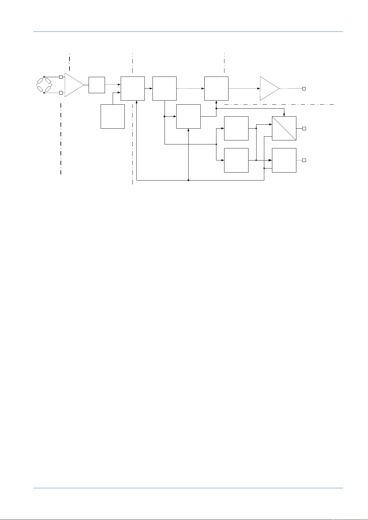
3.2 Block diagram and signal path.............................................................................................................. 9
3.3 IO-Link communication (overview) ....................................................................................................... 10
3.4 Dimensional drawing ............................................................................................................................ 11
4 Transport and storage ................................................................................................................................ 12
4.1 Transport .............................................................................................................................................. 12
4.2 Delivery inspection................................................................................................................................ 12
4.3 Storage ................................................................................................................................................. 12
5 Electrical installation................................................................................................................................... 13
5.1 Connection diagram.............................................................................................................................. 13
5.2 Pin assignment ..................................................................................................................................... 14
6 Commissioning............................................................................................................................................ 15
6.1 Factory settings .................................................................................................................................... 15
6.2 Parameterization of the measuring amplifier ........................................................................................ 16
7 Functions ..................................................................................................................................................... 17
7.1 Process data......................................................................................................................................... 18
7.1.1 Process value Process Data In (PDI) ........................................................................................ 18
7.1.2 Status Bits Process Data In (PDI).............................................................................................. 19
7.1.3 Status Bits Process Data Out (PDO) ......................................................................................... 19
7.2 Observation .......................................................................................................................................... 20
7.2.1 Peak value storage (memory values) ........................................................................................ 21

Baumer List of contents
DAB10 | V1 Operating Manual iii
7.2.2 Sample and Hold ....................................................................................................................... 22
7.3 Parameter ............................................................................................................................................. 23
7.3.1 Parameterization of the sensor characteristics .......................................................................... 23
7.3.2 Low-pass filter............................................................................................................................ 30
7.3.3 Parameterization of the analog output (DAB10-AI, DAB10-AU) ................................................ 31
7.3.4 Parameterization SIO1/2............................................................................................................ 35
7.3.5 Parameterization of the SSCx switching functions .................................................................... 37
7.4 Diagnosis .............................................................................................................................................. 44
7.4.1 Remote operation ...................................................................................................................... 44
7.4.2 Device Status / Error Handling................................................................................................... 44
8 Maintenance................................................................................................................................................. 45
8.1 Cleaning the device .............................................................................................................................. 45
9 Annex............................................................................................................................................................ 46
9.1 Error Handling....................................................................................................................................... 47

1 | About this document Baumer
4 Operating Manual DAB10 | V1
1 About this document
1.1 Purpose
This operating manual (subsequently referred to as manual) allows the safe and efficient han-
dling of the SensControl from Baumer.
The manual is a constituent part of the product. It must be kept in the immediate vicinity of the
product and must be accessible to personnel at all times.
Personnel must have carefully read and understood this manual before beginning any work.
The basic prerequisite for safe working is compliance with all safety instructions and handling
instructions given in this manual.
In addition, the local occupational health and safety regulations and general safety regulations
apply.
The illustrations in this manual are examples only. Deviations are at the discretion of Baumer at
all times.
The product is not intended for permanent installation in automation systems.
NOTICE
The device can cause radio frequency interferences
This is a device of class A. This device can cause radio frequency interferences in residential
areas. In such cases, the operator may be asked to carry out appropriate measures.
1.2 Validity of the manual
The manual is valid for the following product variations:
nDAB10-AI
nDAB10-AL
nDAB10-AU
1.3 Warnings in this manual
Warnings draw attention to injury or material damage. The warnings in this manual indicate dif-
ferent hazard levels:
Symbol Warning term Explanation
DANGER Indicates an immediate danger with high risk that will lead to death
or serious injury if not avoided.
WARNING Indicates a possible danger with medium risk that may lead to
death or (serious) injury if not avoided.
CAUTION Indicates a danger with low risk that could lead to slight or medium
injury if not avoided.
NOTE Indicates a warning of material damage.
INFO Indicates practical information and tips that enable optimal use of
the devices.

Baumer About this document | 1
DAB10 | V1 Operating Manual 5
1.4 Labels in this manual
Identifier Use Example
Dialog element Indicates dialog elements. Click the OK button.
Unique name Indicates the names of products,
files, etc.
Internet Explorer is not supported
in any version.
Code Indicates entries. Enter the following IP address:
192.168.0.250
1.5 Liability limitation
All information and notes in this manual have been compiled in accordance with the applicable
standards and regulations, the state of the art, and our many years of knowledge and experi-
ence.
The manufacturer accepts no liability for damage due to the following reasons:
nNon-observance of the manual
nImproper use
nUse of unqualified personnel
nUnauthorized conversions
The obligations agreed in the delivery contract, the general terms and conditions and the deliv-
ery conditions of the manufacturer and its suppliers, as well as the legal regulations valid at the
time of conclusion of the contract apply.
1.6 Scope of delivery
The scope of delivery includes:
n1 x measuring amplifier
n2 x installation screws
n1 x quickstart
n1 x general information leaflet
In addition, you can find the following information, among other things, in digital format at
www.baumer.com:
nOperating manual
nData sheet
n3D CAD drawing
nQuickstart
nDimensional drawing
nConnection diagram & pin assignment
nCertificates (EU conformity declaration, etc.)

1 | About this document Baumer
6 Operating Manual DAB10 | V1
1.7 Name plate
CH-8501 Frauenfeld, Switzerland
Swiss made
1
2
3
Ill.1: Name plate
1 Item number 2 Denotation
3 Serial number
1.8 Return and repair
In case of complaints, please contact the relevant sales unit.
1.9 Accessories
You can find accessories on the website at:
https://www.baumer.com

Baumer Safety | 2
DAB10 | V1 Operating Manual 7
2 Safety
2.1 Instructions for appropriate use
This product is a precision device designed for the detection of objects, the acquisition of physi-
cal measuring units and for the evaluation of measured values for output in the form of electrical
signals for the higher-level system.
Unless not especially labelled, the product must not be used in potentially explosive atmos-
pheres.
2.2 Set-up
Installation, mounting and adjustment of this product may only be executed by skilled and au-
thorised personnel.
2.3 Installation
Only use the provided mounting devices and accessories for product installation. Unused out-
puts must not be assigned. Unused strands must be isolated. Do not exceed the maximum per-
missible bending radius of the cable. Prior to electrical connection of the product, the system
must be down and not live. Where mandatory, use shielded cables for protection against elec-
tromagnetic interference. Where plug-in connections are added to shielded cables by the cus-
tomer, these plug-in connections must be EMC compliant and the cable shield must be attached
to the connector housing over a large surface area.
2.4 Disposal
Do not dispose of electrical and electronic equipment in household waste. The
product contains valuable raw materials for recycling, which is why the old prod-
uct must be returned to an authorised collecting point for correct disposal/recy-
cling. For further information see www.baumer.com.

3 | Description Baumer
8 Operating Manual DAB10 | V1
3 Description
3.1 General functionality
The measurement amplifier processes signals from sensors with strain gauges. These include,
for example, force, strain, and weighing sensors that are typically equipped with 4 strain gauges
and connected into a (Wheatstone) full bridge.
The output depends on the product variation:
Product variation Output
DAB10-AI nAnalog output (current)
nIO-Link
DAB10-AL nIO-Link
DAB10-AU nAnalog output (voltage)
nIO-Link

Baumer Description | 3
DAB10 | V1 Operating Manual 9
3.2 Block diagram and signal path
Sensor Sensor signal
mV/V
Process value
N, kN, µm/m, mV/V,…
Analog output
in voltage and current values
A/D Input
scaling/
teach-in
Remote
operation
(testing/
simulation)
Low-pass
filter
(8kS/s)
Analog
Output
Adjustment
D/A ±10 V/0 ... 20 mA
C/Q
DI/DQ
SSC1
SSC2 SIO2
IO-Link
SIO1
Signal
memory
(e.g. peak/
sample &
hold
Ill.2: Measuring amplifier block diagram
The basic signal path of the measuring amplifier is as follows:
1. The measuring amplifier feeds the full bridge of the connected sensor and amplifies the re-
sulting passive signal (mV/V).
2. An A/D converter digitizes the passive signal and converts it into a measuring signal (mV/V).
3. The measuring signal is converted into the unit that is measured by the connected sensor
(N, µm/m, kg, t).
4. Low-pass filter (optional): The measuring amplifier smoothes the process value via a param-
eterizable low-pass filter.
5. Memory: The measuring amplifier saves the max./min. process value or the peak peak
process value (delta between min. and max.). In addition, with the sample and hold (S&H)
function the signal is saved at a specific point in time or the subsequent change of the signal
measured.
6. Output: The measuring amplifier presents either the process value, a peak value, or an S&H
value via IO-Link or via an analog output (only for DAB10-AI and DAB10-AU).
The switching thresholds are parameterized via SSC1/2 (Switching Signal Channel). The
switching signals are presented via IO-Link (cyclic data) or via the 2 digital I/O pins.
The I/O pins can be used as input or output:
nInput: Teach-in functions; resetting the peak or S&H storage
nOutput: Values from the SSC1/2, internal alarm or warning signals
All digital functions are also available via the cyclic IO-Link communication.

3 | Description Baumer
10 Operating Manual DAB10 | V1
3.3 IO-Link communication (overview)
The IO-Link communication of the measuring amplifier takes place via cyclic and acyclic data:
nCyclic data:
Data that is transferred by the device automatically and at regular intervals (Process data).
nAcyclic data:
Data that is transferred by the device only upon a command. The device can be parameter-
ized via this data stream (Adjustable data). In addition, the acyclic data allows the transfer of
data for diagnosis (Diagnosis data).
Process data
(cyclic)
Adjustable data
(acyclic) Diagnosis data (acyclic)
Process value
Scale exponent for the process value
SSC1/2
Quality bit
Alarm bit
Sensor setting:
- Unit of the process value
- Nominal measurement range
- Nominal sensitivity
- Offset
Signal processing:
- Filter function
SIO1/2:
- Function selection for SIO1/2
- Input delay for SIO1/2
Analog output (only for DAB10-AI & -AU):
- Signal selection for analog output
- Scaling of the analog output
- Parameterization of the signal range
- Parameterization of the alarm signal
Process value
Min. process value
Max. process value
Peak peak process value. (Delta min. and
max.)
sample and hold process value
sample and hold process value (delta)
CPU temperature
Input signal (mV/V)
Device status
Detailed Device status (up to 10 messages)
Operating time (since response)
Operating time (service life)
Number of response cycles (service life)
Number of tare cycles (service life)
Otros manuales para DAB10
1
Tabla de contenidos
Otros manuales de Amplificador de Baumer