
AVTECH ELECTROSYSTEMS LTD. AVO-9W-B-P-P0E Manual de usuario
INSTRUCTIONS
MODEL AVO-9W-B-P-P0E
10 AMP, 4 – 50 ns PW, 2.5 ns RISE TIME
HI H PERFORMANCE LASER DIODE DRIVER
WITH PLU -IN SOCKET OUTPUT MODULE
SERIAL NUMBER: 14358
A V T E C H E L E C T R O S Y S T E M S L T D .
N A N O S E C O N D W A V E F O R M E L E C T R O N I C S
S I N C E 1 9 7 5
info@avtechpulse.com
http://www.avtechpulse.com/
Tel: 888-670-8729 (USA & Canada)
or +1-613-686-6675 (Worldwide)
BOX 5120, LCD MERIVALE
OTTAWA, CANADA K2C3H5
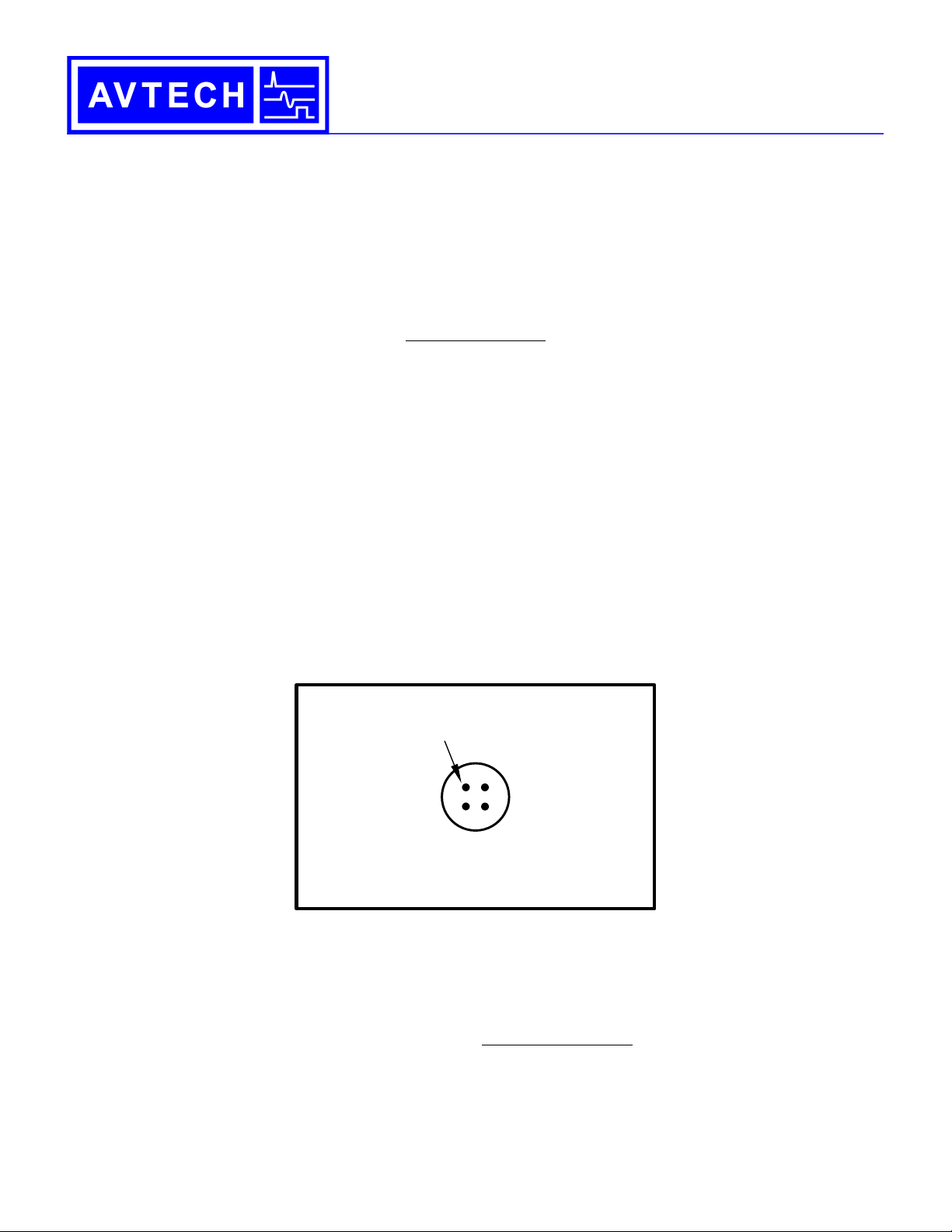
Top left pin socket = Anode
The remaining 3 pin sockets
are connected to ground.
The cathode may be
connected to any of them.
For 5.6 or 9 mm packages
with 2.54 mm pin circle diameter and
0.30-0.43 mm (12-17 mils) pin diameter
AVX-S3C-P0E OUTPUT MODULE, SOCKET VIEW

WARRANTY
Avtech Electrosystems Ltd. warrants products of its manufacture to be free
from defects in material and workmanship under conditions of normal use. If,
within one year after delivery to the original owner, and after prepaid return by
the original owner, this Avtech product is found to be defective, Avtech shall at
its option repair or replace said defective item. This warranty does not apply to
units which have been dissembled, modified or subjected to conditions
exceeding the applicable specifications or ratings. This warranty is the extent of
the obligation assumed by Avtech with respect to this product and no other
warranty or guarantee is either expressed or implied.
TECHNICAL SUPPORT
Phone: 888-670-8729 (USA & Canada)
or +1-613-686-6675 (Worldwide)
E-mail: info@avtechpulse.com
World Wide Web: http://www.avtechpulse.com
2

TABLE OF CONTENTS
WARRANTY.................................................................................................................... 2
TECHNICAL SUPPORT..................................................................................................2
TABLE OF CONTENTS..................................................................................................3
INTRODUCTION............................................................................................................. 5
SPECIFICATIONS...........................................................................................................7
REGULATORY NOTES.................................................................................................. 8
FCC PART 18.......................................................................................................................... 8
EC DECLARATION OF CONFORMITY..................................................................................8
DIRECTIVE 2011/65/EU (RoHS).............................................................................................9
DIRECTIVE 2002/96/EC ( EEE)............................................................................................9
FIRM ARE LICENSING.......................................................................................................10
INSTALLATION.............................................................................................................11
VISUAL CHECK.................................................................................................................... 11
PO ER RATINGS................................................................................................................11
CONNECTION TO THE PO ER SUPPLY...........................................................................11
PROTECTION FROM ELECTRIC SHOCK...........................................................................12
ENVIRONMENTAL CONDITIONS........................................................................................13
LABVIE DRIVERS..............................................................................................................13
FUSES........................................................................................................................... 14
AC FUSE REPLACEMENT...................................................................................................14
DC FUSE REPLACEMENT...................................................................................................15
FUSE RATINGS....................................................................................................................15
FRONT PANEL CONTROLS........................................................................................16
REAR PANEL CONTROLS..........................................................................................18
GENERAL INFORMATION...........................................................................................20
MINIMAL TEST ARRANGEMENT - ITHOUT OUTPUT MODULE.....................................20
NORMAL TEST ARRANGEMENT........................................................................................20
AMPLITUDE CONTROL.......................................................................................................23
BASIC PULSE CONTROL....................................................................................................23
TRIGGER MODES................................................................................................................ 24
GATING MODES...................................................................................................................25
PROTECTING YOUR INSTRUMENT............................................................................26
DO NOT EXCEED 20 kHz.....................................................................................................26
3

USE A 50Ω LOAD................................................................................................................. 26
OPERATIONAL CHEC ...............................................................................................27
PROGRAMMING YOUR PULSE GENERATOR...........................................................30
KEY PROGRAMMING COMMANDS....................................................................................30
ALL PROGRAMMING COMMANDS.....................................................................................31
MECHANICAL INFORMATION.....................................................................................33
TOP COVER REMOVAL.......................................................................................................33
RACK MOUNTING................................................................................................................33
ELECTROMAGNETIC INTERFERENCE..............................................................................33
MAINTENANCE............................................................................................................ 34
REGULAR MAINTENANCE..................................................................................................34
CLEANING............................................................................................................................ 34
TRIGGER DAMAGE.............................................................................................................. 34
WIRING DIAGRAMS.....................................................................................................35
IRING OF AC PO ER.......................................................................................................35
PCB 158R7 - LO VOLTAGE PO ER SUPPLY................................................................36
PCB 235D - HIGH VOLTAGE DC PO ER SUPPLY............................................................37
PCB 216F - PRF/P T EAKING PCB................................................................................38
PCB 104H - KEYPAD / DISPLAY BOARD...........................................................................39
MAIN IRING....................................................................................................................... 40
PERFORMANCE CHEC SHEET.................................................................................41
Manual Reference: /fileserver1/officefiles/instructword/avo-9/AVO-9W-B-P-P0E,ed1.odt.
Last modified July 26, 2023.
Copyright © 2023 Avtech Electrosystems Ltd, All Rights Reserved.
4

INTRODUCTION
The AVO-9W-B-P-P0E is a high performance, PIB and RS232-equipped instrument
capable of generating up to +10A of current into diode loads, at repetition rates of up to
20 kHz. The pulse width is adjustable from 4 to 50 ns. The rise times are 2.5 ns or less,
and the fall times are 3.5 ns or less.
The AVO-9W-B-P-P0E consists of a mainframe unit and an AVX-S3C series output
module, which provides a socket into which the user's laser diode may be inserted. The
mainframe generates voltage pulses of up to +125V. The output module connects to
the instrument mainframe using two parallel detachable coaxial cables. The output
module contains the necessary elements to match the laser diode to the pulse
generator mainframe, including a current-doubling transformer. A DC bias current of 0
to 100 mA may be applied to the laser diode by applying the desired DC current to a
solder terminal on the output module. The output modules include an SMA output
connector that provides an attenuated coincident replica of the diode current.
The AVX-S3C-P0E output module is designed to accommodate a 2, 3 or 4 pin 5.6mm
or 9mm package with a 2.54mm pin circle diameter. Four pin sockets are provided,
which accept pins of 0.30-0.43 mm diameter (12-17 mils). A positive pulse signal is
applied to one pin socket (for the anode). The other three pin sockets (one of which will
be the cathode) are grounded. The diode should have a parasitic resistance (dV/dI at
lasing) of < 1 Ohms for proper impedance matching.
The AVO-9W-B-P-P0E is a highly flexible instrument. Aside from the internal trigger
source, it can also be triggered or gated by external TTL-level signals. A front-panel
pushbutton or a computer command can also be used to trigger the instrument.
5
Top left pin socket = Anode
The remaining 3 pin sockets
are connected to ground.
The cathode may be
connected to any of them.
For 5.6 or 9 mm packages
with 2.54 mm pin circle diameter and
0.30-0.43 mm (12-17 mils) pin diameter
AVX-S3C-P0E OUTPUT MODULE, SOCKET VIEW

The AVO-9W-B-P-P0E features front panel keyboard and adjust knob control of the
output pulse parameters along with a four line by 40-character backlit LCD display of
the output amplitude, pulse width, pulse repetition frequency, and delay. The instrument
includes memory to store up to four complete instrument setups. The operator may use
the front panel or the computer interface to store a complete “snapshot” of all key
instrument settings, and recall this setup at a later time.
This instrument is intended for use in research, development, test and calibration
laboratories by qualified personnel.
6

SPECIFICATIONS
Model1: AVO-9W-B-P-P0E
Maximum amplitude2,6: 10 Amp
Maximum voltage output of
mainframe (VMAINFRAME):
125V
(to 25Ω)
RS + RDIODE: 6.2Ω
Transformer ratio, N: 2
Allowed load voltage range: 0 to 3V. (Contact Avtech if your diode has a higher forward voltage drop)
Pulse width (FWHM): 4 - 50 ns
Maximum duty cycle: N/A
Maximum PRF4: 20 kHz
Rise time (20%-80%): ≤ 2.5 ns
Fall time (20%-80%): ≤ 3.5 ns
Related 50Ω series: AVO-2W
Included output module: AVX-S3C
Polarity3: Positive or negative (specify)
PIB and RS-232 control1: Standard on -B units.
LabView drivers: Check http://www.avtechpulse.com/labview for availability and downloads
Ethernet port, for remote
control using VXI-11.3, ssh,
telnet, & web:
Included. Recommended as a modern alternative to PIB / RS-232.
See http://www.avtechpulse.com/options/vxi for details.
Propagation delay: ≤ 150 ns (Ext trig in to pulse out)
Jitter: ± 35 ps ± 0.015% of sync delay (Ext trig in to pulse out)
DC offset or bias insertion: Apply required DC bias current in the range of ± 100 mA to solder terminal on output module.
Sync delay: Variable 0 to ±1 second, sync out to pulse out
Sync output: + 3 Volts, 100 ns, will drive 50 Ohms
ate input: Synchronous or asynchronous, active high or low, switchable. Suppresses triggering when active.
Trigger required: External trigger mode: TTL-level pulse (LO = 0V, HI = 3-5V), ≥ 10 ns
Connectors: Out:
Other:
User-specified socket. Sockets can be provided for 5.6 mm, 9 mm, butterfly, and other packages.
Trig, Sync, ate: BNC, Monitor: SMA
Recommended accessory kit: Add the suffix "-AK2" to the model number to include the recommended accessory kit.
Consists of one SMA 12 Hz 20 Watt attenuator (20 dB) and two SMA 18 Hz 2 Watt
attenuators (10 & 20 dB) for use on the output, and two 50 Ohm, 1 Hz, 1 Watt
feed-through terminators (one SMA, one BNC) for use on external trigger inputs.
Power requirements: 100 - 240 Volts, 50 - 60 Hz
Dimensions: Mainframe:
(H×W×D) Output module:
100 x 430 x 375 mm (3.9” x 17” x 14.8”) , anodized aluminum, with blue plastic trim
41 x 66 x 76 mm (1.6” x 2.6” x 3.0”), cast aluminum, blue enamel
Temperature range: +5°C to +40°C
1) -B suffix indicates IEEE-488.2 PIB and RS-232 control of amplitude and frequency. See http://www.avtechpulse.com/gpib/ for details.
2) For operation at amplitudes of less than 20% of full-scale, best results will be obtained by setting the amplitude near full-scale and using external attenuators on the output,
between the mainframe and the output module.
3) Indicate desired polarity by suffixing model number with -P or -N (i.e. positive or negative).
4) The minimum PRF of the internal oscillator is 1 Hz on -B units. There is no minimum in the external trigger mode.
7

RE ULATORY NOTES
FCC PART 18
This device complies with part 18 of the FCC rules for non-consumer industrial,
scientific and medical (ISM) equipment.
This instrument is enclosed in a rugged metal chassis and uses a filtered power entry
module (where applicable). The main output signal is provided on a shielded connector
that is intended to be used with shielded coaxial cabling and a shielded load. Under
these conditions, the interference potential of this instrument is low.
If interference is observed, check that appropriate well-shielded cabling is used on the
output connectors. Contact Avtech (info@avtechpulse.com) for advice if you are unsure
of the most appropriate cabling. Also, check that your load is adequately shielded. It
may be necessary to enclose the load in a metal enclosure.
If any of the connectors on the instrument are unused, they should be covered with
shielded metal “dust caps” to reduce the interference potential.
This instrument does not normally require regular maintenance to minimize interference
potential. However, if loose hardware or connectors are noted, they should be
tightened. Contact Avtech (info@avtechpulse.com) if you require assistance.
EC DECLARATION OF CONFORMITY
We Avtech Electrosystems Ltd.
P.O. Box 5120, LCD Merivale
Ottawa, Ontario
Canada K2C 3H5
declare that this pulse generator meets the intent of Directive 2004/108/E for
Electromagnetic Compatibility. Compliance pertains to the following specifications as
listed in the official Journal of the European Communities:
EN 50081-1 Emission
EN 50082-1 Immunity
8

and that this pulse generator meets the intent of the Low Voltage Directive 2006/95/EC.
Compliance pertains to the following specifications as listed in the official Journal of the
European Communities:
EN 61010-1:2001 Safety requirements for electrical equipment for
measurement, control, and laboratory use
DIRECTIVE 2011/65/EU (RoHS)
We Avtech Electrosystems Ltd.
P.O. Box 5120, LCD Merivale
Ottawa, Ontario
Canada K2C 3H5
declare that, to the best of our knowledge, all electrical and electronic equipment (EEE)
sold by the company are in compliance with Directive 2011/65/EU of the European
Parliament and of the Council of 8 June 2011 on the restriction of the use of certain
hazardous substances in electrical and electronic equipment (also known as “RoHS
Recast”). In addition, this declaration of conformity is issued under the sole
responsibility of Avtech Electrosystems Ltd. Specifically, products manufactured do not
contain the substances listed in the table below in concentrations greater than the listed
maximum value.
Material/Substance Threshold level
Lead (Pb) < 1000 ppm (0.1% by mass)
Mercury (Hg) < 1000 ppm (0.1% by mass)
Hexavalent Chromium (Cr6+) < 1000 ppm (0.1% by mass)
Polybrominated Biphenyls (PBB) < 1000 ppm (0.1% by mass)
Polybrominated Diphenyl ethers (PBDE) < 1000 ppm (0.1% by mass)
Cadmium (Cd) < 100 ppm (0.01% by mass)
Bis(2-ethylhexyl) phthalate (DEHP) < 1000 ppm (0.1% by mass)
Butyl benzyl phthalate (BBP) < 1000 ppm (0.1% by mass)
Dibutyl phthalate (DBP) < 1000 ppm (0.1% by mass)
Diisobutyl phthalate (DIBP) < 1000 ppm (0.1% by mass)
DIRECTIVE 2002/96/EC (WEEE)
European customers who have purchased this equipment directly from Avtech will have
completed a “WEEE Responsibility Agreement” form, accepting responsibility for WEEE
compliance (as mandated in Directive 2002/96/EC of the European Union and local
9

laws) on behalf of the customer, as provided for under Article 9 of Directive
2002/96/EC.
Customers who have purchased Avtech equipment through local representatives
should consult with the representative to determine who has responsibility for WEEE
compliance. Normally, such responsibilities with lie with the representative, unless other
arrangements (under Article 9) have been made.
Requirements for WEEE compliance may include registration of products with local
governments, reporting of recycling activities to local governments, and financing of
recycling activities.
FIRMWARE LICENSIN
Instruments with firmware versions 5.00 or higher use open-source software internally.
Some of this software requires that the source code be made available to the user as a
condition of its licensing. This source code is available upon request (contact
info@avtechpulse.com).
Earlier firmware versions do not contain any open source software.
10
Tabla de contenidos
Otros manuales de Instrumento de medición de AVTECH ELECTROSYSTEMS LTD.

Manuales populares de Instrumento de medición de otras marcas


Endress+Hauser
Endress+Hauser Proline Promag 50 Especificaciones técnicas

Siemens
Siemens SITRANS F Coriolis FCT030 Manual de lista de piezas

KLINGER
KLINGER CMF V Series Manual de usuario

EXFO
EXFO FTB-2 Manual de operación y mantenimiento

Keysight
Keysight M8290A Manual de usuario

ADTEK
ADTEK MW-5 Manual de usuario