2
WWW.AUTOLOC.COMTECH SUPPORT: 503.693.1918
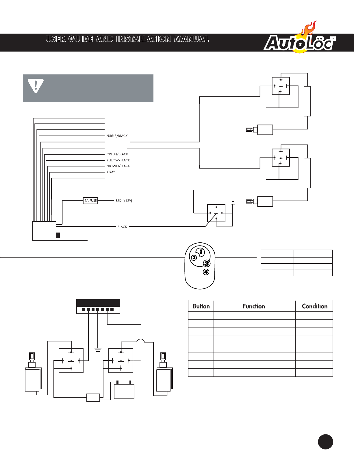
SHAVE DOOR HANDLE SYSTEMS
AUTSVPRO
©2019 The Hoffman Group L. L. C. All rights reserved. AUTSVPRO Rev5 2 of 4 01/22/2019
The above instructions are for reference only. THG LLC is not responsible for any inaccuracies in the above instructions. THG LLC is also not responsible for any property damage or personal injuries resulting from the
above instructions. Installation by qualified automotive professionals is highly recommended.
GREEN/WHITE
ETIHW/EULB
MULTI-FUNCTION KITS
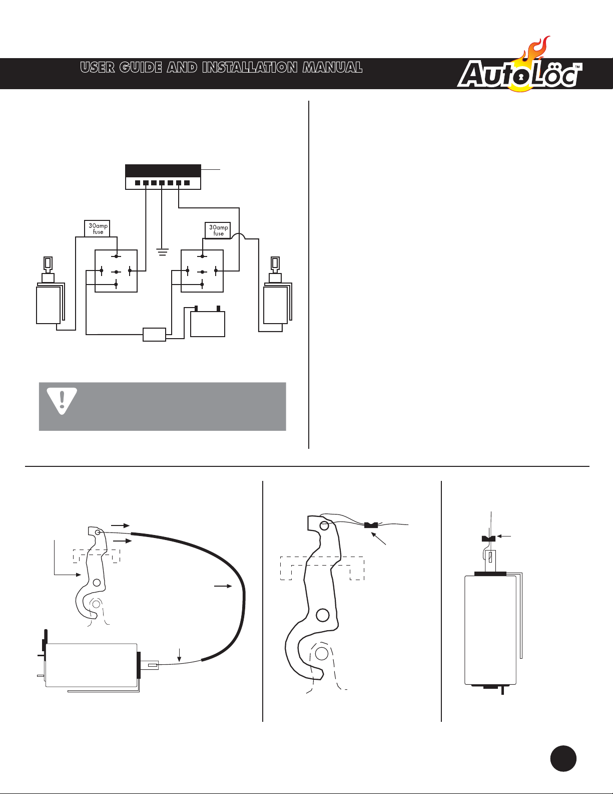
DOOR RELAY DOOR RELAY
+ –
REVIRD
REGNESSAP
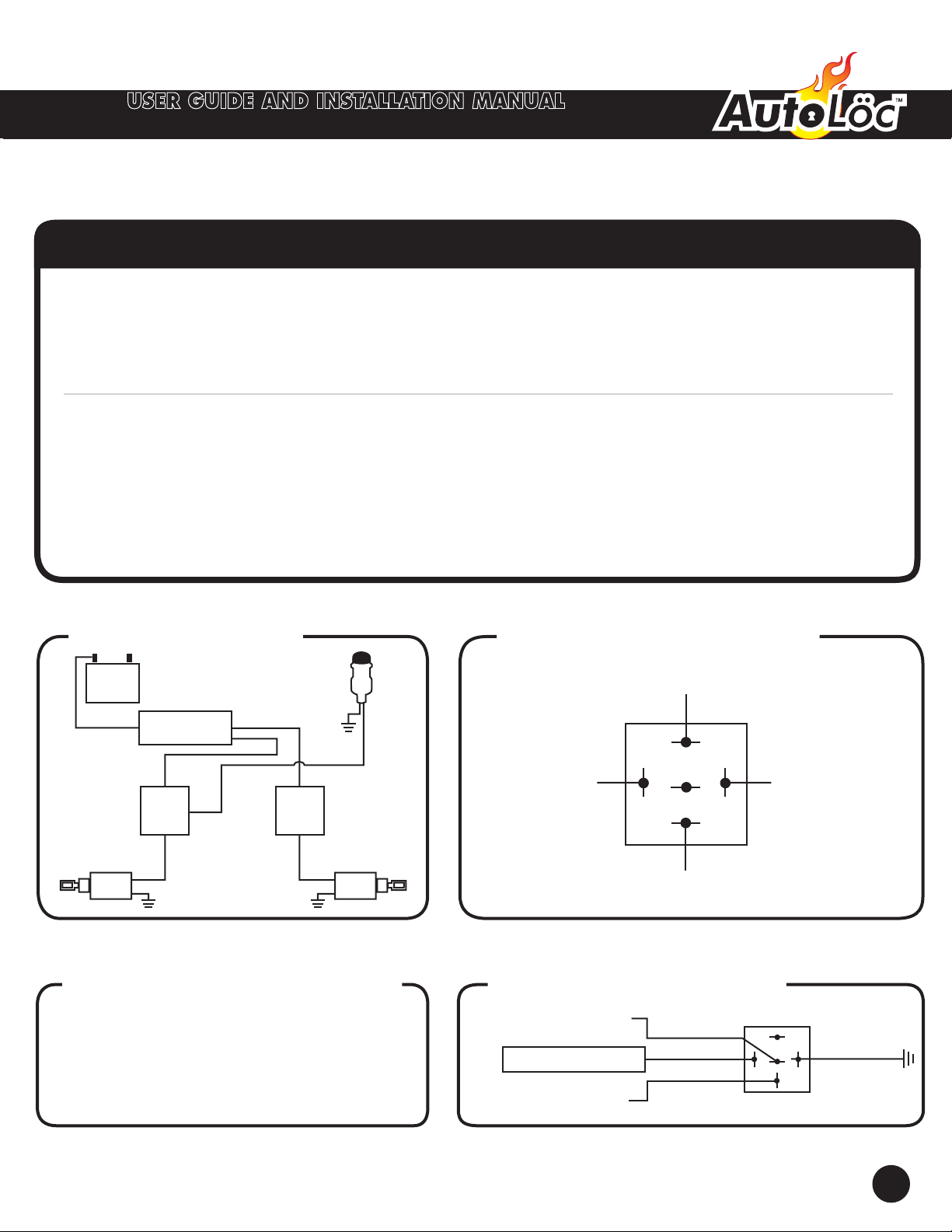
87
87a
30
86
85 87
87a
30
86
85
FUSE
30A
Remote Receiver
Connector
Please reference the
receivers wiring diagram for
all other wire connections.
IMPORTANT!
IMPORTANT NOTICE: Upon completion of installation,
you may have extra unused wires on the wiring
harness. Do not be concerned. These wires are used
for features available on other models.
+12V
87
87a
30
86
85
RELAY
Solenoid
DRIVER
DOOR SOLENOID
+12V
87
87a
30
86
85
RELAY
Solenoid
PASSENGER
DOOR SOLENOID
(CH1 – 500 mA)
(CH2 – 500 mA)
(CH3 – 500 mA)
(CH4 – 500 mA)
(STARTER/IGNITION KILL OUTPUT)
RED/BLACK (CH5 – 500mA)
VALET SWITCH
WHITE/BLACK (CH6 – 500mA)
ORANGE (FOR PROGRAMMING ONLY)
YELLOW (12V CONSTANT POWER - FOR PROGRAMMING ONLY)
Keyless
Unit
CHASSIS
GROUND
SAFETY
RELAY 87
87a
30
86
85
SWITCH IGNITION POWER
1 Drivers Door Anytime
2 Passengers Door Anytime
3 1st channel output Anytime
4 2nd channel output Anytime
1 + 3 3rd channel output Anytime
2 + 4 4th channel output Anytime
1 + 2 5th channel output Anytime
3 + 4 6th channel output Anytime
BLACK
CODE LEARNING
a. Connect 12 volt constant power to yellow wire on receiver. Press and hold valet button
for 3 - 5 seconds. The orange wire will receive a momentary ground signal to indicate
code learning mode. A test light can be used to see the ground signal. The test light will
flash once to indicate code learning mode achieved. Press any button on the remote to
be programed within 30 seconds. Test light will flash again to indicate remote has been
accepted. Up to 4 remotes may be learned. Disconnect power to yellow wire. System
will automatically exit programing mode.
ALWAYS USE PROTECTION
Make sure to always protect your
connections to the battery, using the
appropirate fuses or circuit breakers.
PART # PROTECTION
AUTSL35 30 Amp Fuse
AUTSL50 40/50 Amp CB
AUTSL75/100 60/70 Amp CB
CB = Circuit Breaker
*ALL OUPUTS ARE NEGATIVE
Ground signals.
Connect to groundside of circuit.
ANTENNA
CIRCUIT BREAKER
40 AMP (NOT INCLUDED)
CIRCUIT BREAKER
40 AMP (NOT INCLUDED)
GREEN/WHITE
BLUE/WHITE