SENSOR INSTALLATION FOR VERTICAL WINDLASSES
For accurate rope and chain counting the AA560 must be tted using the grey AutoAnchor
sensor (#9067) supplied in the kit. Some windlasses are pretted with a reed switch sen-
sor. The reed switch sensor can be used for chain only counting.
The sensor is tted into the windlass deckplate. Some windlasses are predrilled for the
sensor. Others have a dimple or mark to show where the sensor should be tted. Check
with the AutoAnchor or windlass supplier if you are not sure where to drill for the sensor.
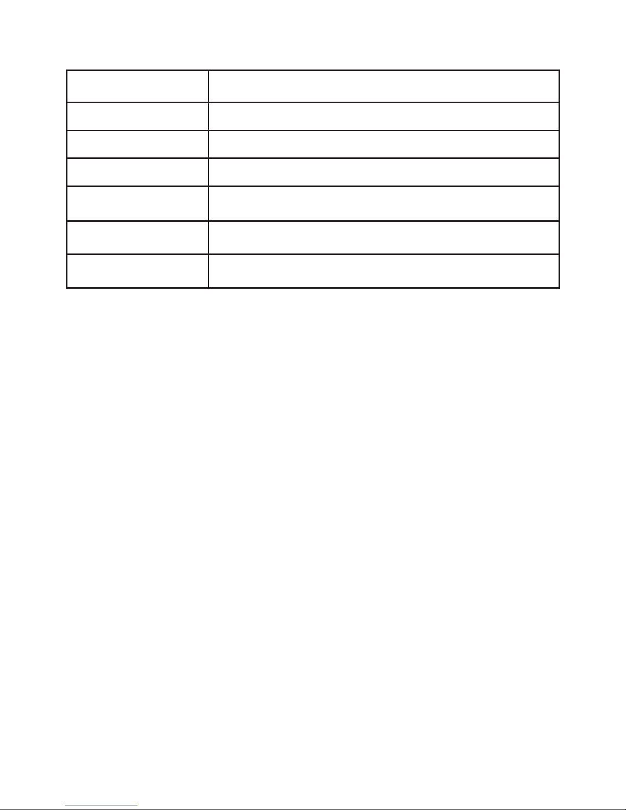
Sensor Position for Vertical Windlasses Using Chain Only Rode: The sensor hole
can be drilled anywhere on the deckplate provided it is in alignment with the magnet in the
chainwheel and the gap between the sensor and magnet will be correct.
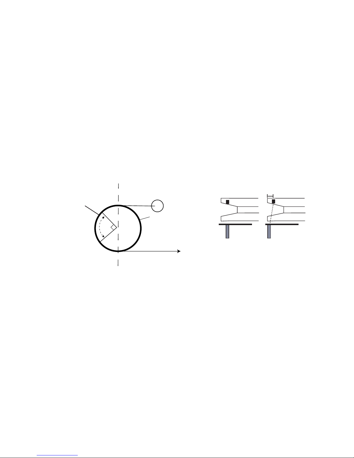
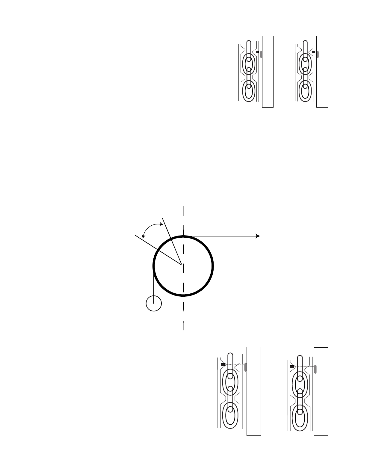
Sensor Position for Vertical Windlasses Using Rope and Chain Rode: The hole must
be within the sensor position range at the stern end of the windlass (See Fig 5). The
sensor must also be aligned with the magnet so that the rode passes between the
sensor and the magnet. The centre of the magnet and the centre of the sensor may be up
to 10mm out of direct alignment. (See Fig 6)
Drilling the Deckplate: If the windlass is not factory drilled, drill a hole 10.3 mm (13/32”)
diameter through the windlass deckplate. Some windlasses will be marked for sensor
tting. Check the AutoAnchor drilling templates supplied with this kit.
Drilling the Deck: Before drilling into the deck, ensure there is nothing below the deck
that could be damaged and that any hole you drill will not weaken the boat’s structure. Drill
a hole 10.3mm (13/32”) diameter through the deck. Ensure this hole is directly in line with
the sensor hole in the deckplate.
Fitting the Sensor: Do not force the sensor into the hole. Hammering the sensor head
can damage the internal electronics. Ensure the sensor head is positioned so that it will not
be hit by the chainwheel during windlass operation and that it is at least 300mm (1ft) away
from the battery and motor cables. Secure the sensor using a good quality neutral cure
silicone or a strong adhesive eg. Sikaex 291 or 3M 5200.
Sensor Connection: Refer to the wiring diagrams for the sensor connection. If the
AutoAnchor plug in cable is not used all sensor wires must be soldered and sealed
in adhesive heat shrink tubing. Refer to the sensor splice sheet. Do not leave the
cable hanging loose, it must be tied in place with cable ties. Extension cable and eld
connectors are available for the AutoAnchor plug in sensor connections.
Sensor Position Range
Fig 5 Fig 6 Sensor & Magnet Alignment
10mm
Sensor
Magnet
Sensor
Magnet
6