
Audiovox KCD3180 Manual de usuario
- 1 -
SAFETYPRECAUTIONS
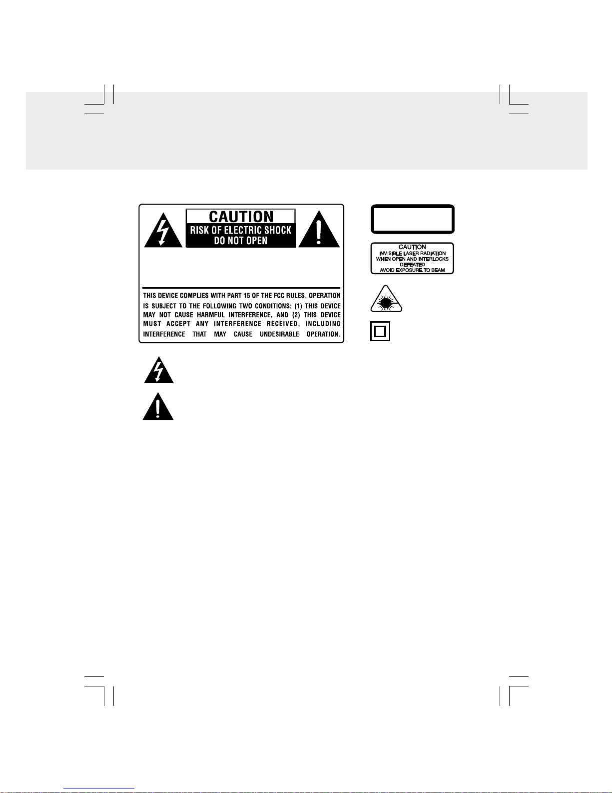
DO NOT EXPOSE THIS UNIT TO RAIN OR MOISTURE
WARNING: SHOCK HAZARD - DO NOT OPEN
AVIS: RISQUE DE CHOC ÉLECTRIQUE - NE PAS OUVRIR
CLASS 1 LASER PRODUCT
APPAREIL À LASER DE CLASSE 1
PRODUCTO LASER DE CLASE 1
This product
contains a low power
laser device.
WARNING: TO REDUCE THE RISK OF FIRE OR ELECTRIC SHOCK, DO NOT EXPOSE
THIS APPLIANCE TO RAIN OR MOISTURE.
ON SAFETY
•Before operating, make sure the voltage requirement of the unit matches your local
voltage.
•Disconnect the plug as soon as immediately unplug the unit if liquid spills into or onto
the unit, or if an object enters the unit. The unit should not be used until being checked
by experts.
•Do not open the cabinet. Lasers used in rays employed by the unit may damage your
eyes. Any servicing should be done by qualified service personnel.
•When you are not going to use the unit for a long period of time, disconnect the power
cord.
ON PLACEMENT
•Do not leave, mount or use the unit in places which are extremely hot, cold, dusty, or
humid.
•Allow adequate air circulation to prevent internal heat build-up. Do not place the unit
on a surface or near materials (a curtain ex. rugs, blankets, curtains, etc.) which might
block the ventilation holes.
ON CONDENSATION
•When left in a heated room where it is warm and damp, water droplets or condensation
may form inside the CD player. When there is condensation inside the unit, the unit may
not function normally. Let it stand for 1 to 2 hours before turning the power on, or
gradually heat the room up and dry the unit before use.
The lightning flash with an arrowhead symbol, within the equilateral triangle,
is intended to alert the user to the presence of uninsulated "dangerous voltage"
within the product's enclosure that may be of sufficient magnitude to cause an
electric shock.
The exclamation point within the equilateral triangle intended to alert the user
to the presence of important operating and maintenance (servicing) instructions
in this owner manual.
The symbol for Class II
(Double Insulation)
- 2 -
FCC Information (FOR USERS IN USA)
This equipment has been tested and found to comply with the limits for a Class B digital
device, pursuant to Part 15 of the FCC Rules. These limits are designed to provide
reasonable protection against harmful interference in a residential installation. This
equipment generates, uses and can radiate radio frequency energy and, If not installed
and used in accordance with the instructions, may cause harmful interference to radio
communications. However, there is no guarantee that interference will not occur in a
particular installation. If this equipment does cause harmful interference to radio or
television reception, which can be determined by turning the equipment off and on, the
user is encouraged to try to correct the interference by one or more of the following
measures:
- Reorient or relocate the receiving antenna.
- Increase the separation between the equipment and receiver.
- Connect the equipment into an outlet that is on a circuit different from the one the
receiver is connected.
- Consult the dealer or an experienced radio / TV technician for help.
You are cautioned that any changes or modifications not expressly approved
in this manual could void your authority to operate this equipment.
SAFETYPRECAUTIONS
RECOGNIZE SAFETY SYMBOLS, WORDS AND LABELS
What You Need to Know About Safety Instructions
Warning and Important Safety Instructions appearing in this manual are not meant to
cover all possible conditions and situations that may occur. Common sense, caution and
care must be exercised when operating, mounting, or cleaning this unit.
Always contact your dealer, distributor, service agent or manufacturer about problems
or conditions you do not understand.
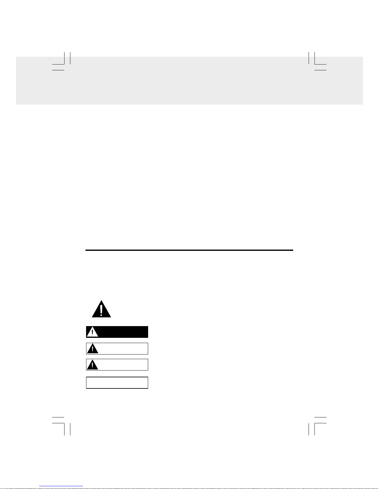
This is the safety alert symbol. It is used to alert you to potential personal
injury hazards. Obey all safety messages that follow this symbol to avoid
possible injury or death.
DANGER indicates an imminently hazardous situation which,
if not avoided, will result in death or serious injury.
WARNING indicates a potentially hazardous situation which,
if not avoided, could result in death or serious injury.
CAUTION indicates a potentially hazardous situation which,
if not avoided, may result in minor or moderate injury.
CAUTION used without the safety alert symbol indicates a
potentially hazardous situation which, if not avoided, may
result in property damage.
DANGER
WARNING
CAUTION
CAUTION

- 3 -
IMPORTANT SAFETY INSTRUCTIONS
1. This portable luminaire has a polarized plug (one blade is wider than the other) as a
feature to reduce the risk of electric shock. This plug will fit in a polarized outlet only
one way, if the plug does not fit, contact a qualified electrician. Never use with an
extension cord unless plug can be fully inserted. Do not alter the plug.
2. Read these instructions.
3. Keep these instructions.
4. Heed all warnings.
5. Follow all instructions.
6. Do not use this apparatus near water.
7. Clean only with a dry cloth.
8. Do not block any of ventilation openings. Install in accordance with the manufacturer's
instructions.
9. Do not install near any heat sources such as radiators, heat registers, stoves, or
other apparatus (including amplifiers) that produce heat.
10. Do not defeat the safety purpose of the polarized or grounding-type plug. A polarized
plug has two blades with one wider than the other. A grounding type plug has two
blades and a third grounding prong. The wide blade or the third prong are provided
for your safety. When the provided plug does not fit into your outlet, consult an
electrician for replacement of the obsolete outlet.
11. Protect the power cord from being walked on or pinched particularly at plugs,
convenience receptacles, and the point where they exit from the apparatus.
12. Only use attachments/accessories specified by the manufacturer.
13. Use only with a cart, stand, tripod, bracket, or table specified by the manufacturer,
or sold with the apparatus. When a cart is used, use caution when moving the cart/
apparatus combination to avoid injury from tip-over.
14. Unplug this apparatus during lightning storms or when unused for long periods of
time.
15. Refer all servicing to qualified service personnel. Servicing is required when the
apparatus has been damaged in any way, such as power-supply cord or plug is
damaged, liquid has been spilled or objects have fallen into the apparatus, the
apparatus has been exposed to rain or moisture, does not operate normally, or has
been dropped.

- 4 -
TABLE OF CONTENTS
SAFETY PRECAUTIONS...........................................................................................1-2
IMPORTANT SAFETY INSTRUCTIONS..........................................................................3
TABLE OF CONTENTS......................................................................................................4
PACKAGE CONTENTS....................................................................................................5
MOUNTING INSTRUCTIONS...................................................................................6-8
FRONT PANEL CONTROLS............................................................................................9
REMOTE CONTROL.................................................................................................9-10
USING THE COUNTERTOP LIGHT................................................................................11
SETTING THE CLOCK...................................................................................................12
CD PLAYBACK........................................................................................................12-13
CD REPEAT PLAYBACK.................................................................................................13
CD PROGRAMMABLE PLAYBACK...............................................................................14
LISTENING TO THE RADIO...........................................................................................15
SETTING THE COOKING TIMER....................................................................................16
DISPLAYFUNCTION......................................................................................................16
TROUBLESHOOTING,CARE & MAINTENANCE......................................................17
SPECIFICATIONS..........................................................................................................17
- 5 -
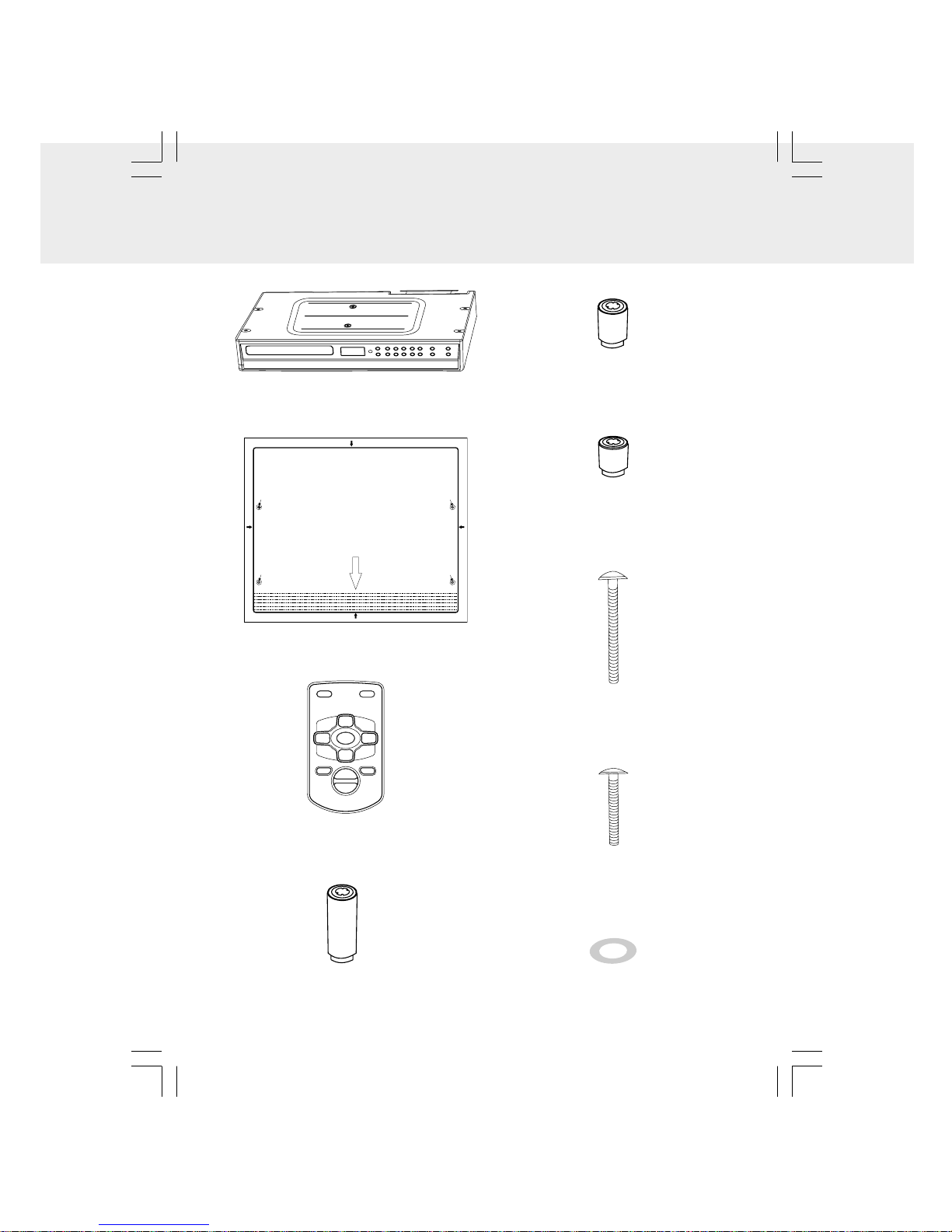
PACKAGECONTENTS
D. (4) - 1.06" (27mm) spacers
A. (1) - Main Unit
B. (1) - Mounting Template
C. (1) - Remote Control
E. (4) - .57" (14.4mm) spacers
F. (4) - .32" (8.2mm) spacers
H. (4) - #M 5 x 40 mm screws
G. (4) - #M 5 x 69 mm screws
If no overhang, front edge of template should
be even with front edge of cabinet.
PLEASE READ MOUNTING INSTRUCTIONS
IN USER MANUAL BEFORE INSTALLING UNIT.
ANTES DE INSTALAR LA UNIDAD, POR FAVOR
LEA LAS INSTRUCCIONES DE MONTAJE QUE
APARECEN EN EL MANUAL DEL USUARIO.
Doble las instrucciones para medir el grosor de la
saliente del mueble.
Fold guidelines for measuring thickness of cabinet
overhang.
FRENTE
FRONT
Si no está sobresaliente, el borde frontal de la plantilla
debe estar nivelado con el borde frontal del mueble.
Taladre aquí
Drill Here Taladre aquí
Drill Here
Cut out on solid black line. Corte en la línea negra.
810-318095-030
Cut out on solid black line. Corte en la línea negra.
Taladre aquí
Drill Here
Taladre aquí
Drill Here
Cut out onsolid black line.Corte en la línea negra.
Cut out on solid black line. Corte en la línea negra.
I. (4) - Double side tape washers
- 6 -
MOUNTINGINSTRUCTIONS
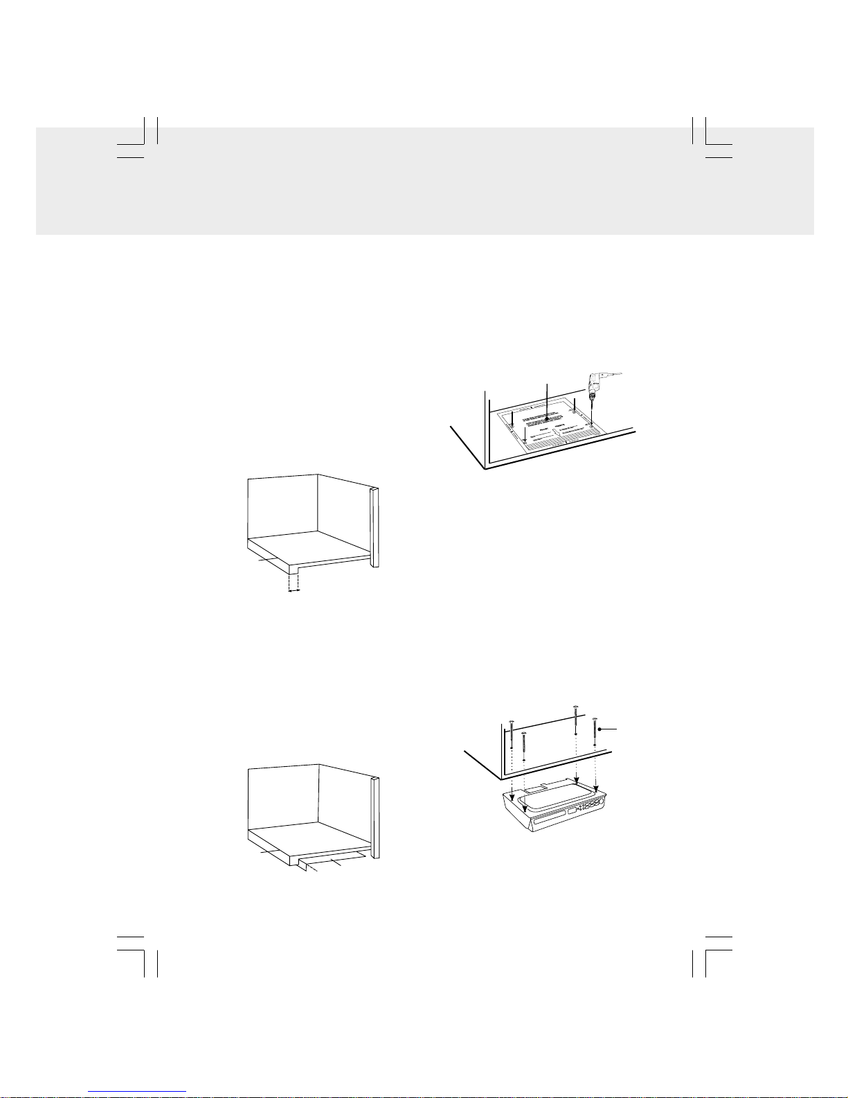
b) Fold the Mounting Template along the
guideline that is closest to the
thickness of your cabinet overhang.
c) Tape Mounting Template to the
underside of the cabinet with the
folded portion of the Mounting
Template flush up against the cabinet
overhang (see Figure 2). Go to
STEP 2.
If your cabinet DOES have an overhang:
a) Measure the thickness of the cabinet
overhang (see Figure 1).
STEP1
If your cabinet does NOT have an
overhang:
a) Place the Mounting Template in the
desired location inside or underneath
the cabinet (whichever has less
obstructions, and will be easier for
you to reach to drill holes), flush with
the front edge of the cabinet and
tape it down. Go to STEP 2.
Cabinet Bottom
Front
edge
Figure 1
Cabinet Bottom
Front
edge
Template
Figure 2
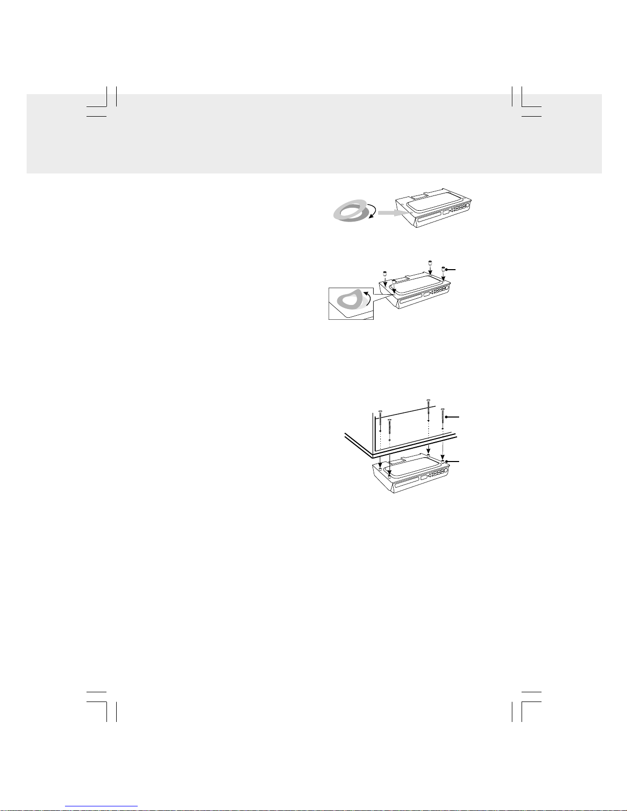
STEP2
Use an electric drill with a ¼” drill bit (not
included) to drill all four holes marked on
the Mounting Template (see Figure 3). To
reduce splintering, please a small piece of
masking tape over each hole location
before drilling. Go to STEP 3.
Template
STEP3
If your cabinet does NOT have an overhang:
a)Eight screws are included with this
unit, but you will only need four of
them. Select the screw length which
will go completely through your
cabinet bottom, and provide at least
3/8" of thread to screw into the main
unit.
b)Insert the four selected screws
through each hole from the inside of
the cabinet going down (see Figure4).
Figure 3
Figure 4
(Continued on next page)
Mounting
Screw
- 7 -
MOUNTINGINSTRUCTIONS
If your cabinet DOES have an overhang:
a) Eight screws are included with this
unit, but you will only need four of
them. Select the screw length which
will go completely through your
cabinet bottom, and extend at least
3/8" past the bottom of your cabinet
overhang.
b) This unit includes three sets of four
spacers of various lengths. The
spacers can be put together to form
longer spacers to accommodate
various cabinet overhang
thicknesses. Determine the best
combination of spacers which is
equal to or longer than the cabinet
overhang thickness.
c) Hold the unit up against the bottom of
the cabinet, and align the four holes on
the top of the unit with the screws.
Partially tighten each screw, but do
not fully tighten the screws until all of
them have been started.
d) Gently tighten each screw until they
are firmly holding the unit in place.
Go to STEP 4.
(Continued from previous page)
(Continued on next page)
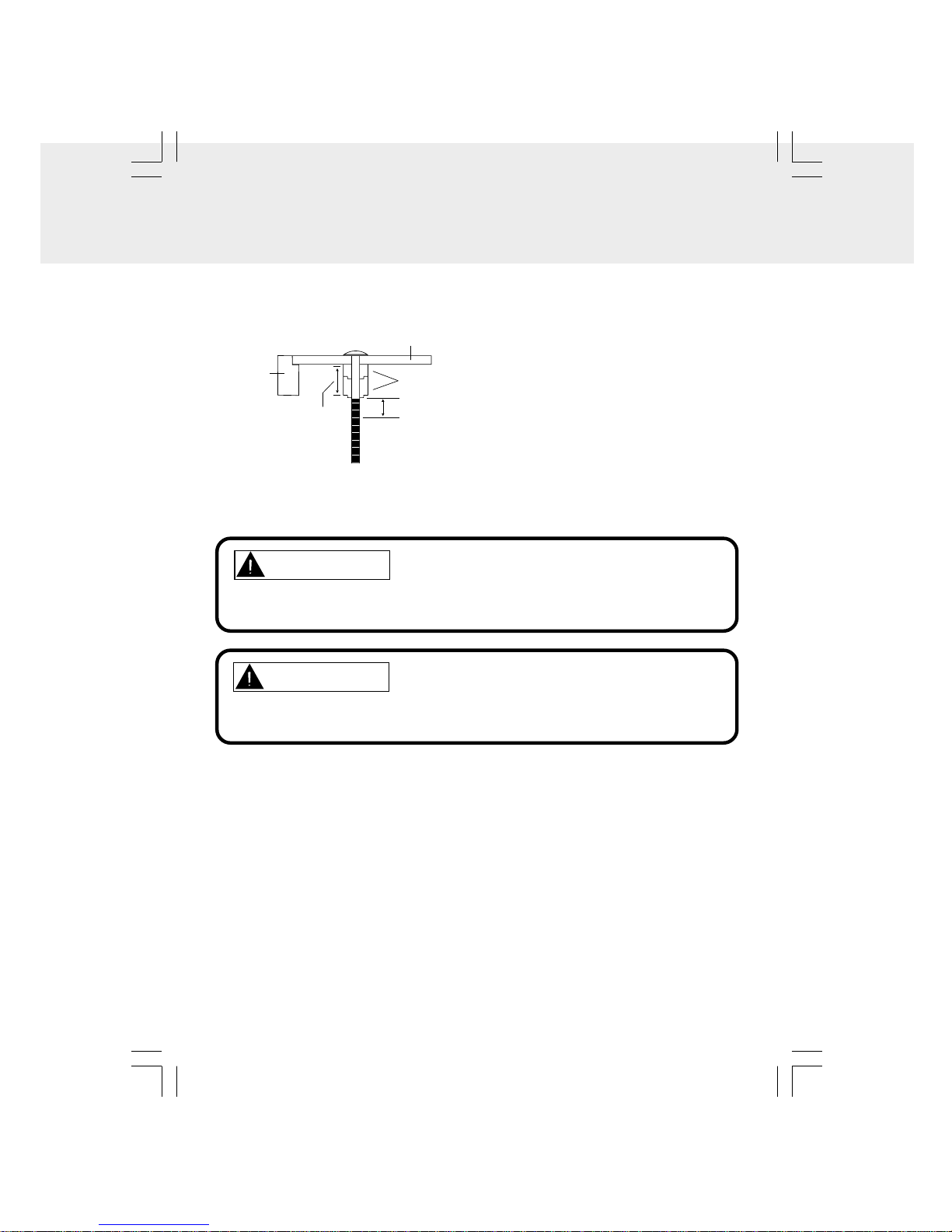
c) Mounting with spacers & double
side tape washers (optional). If
use the spacers, please use the
supplied tape washers to get easy
alignment.
Please remove one side of the
protective tab from the tape washers
first, and align the tape washers to
the holes and flush with them, then
remove another side of the protective
tab from the tape washer. Align the
spacers (optional) onto the tape
washer (see Figure 5 & 6).
d) Insert the four selected screws
through each hole from the inside
of the cabinet going down (see
Figure 7).
Mounting
Screw
Spacer
(Optional)
Figure 7
Spacer
(Optional)
Remove another side of the protective
tab and align the spacers onto them.
Remove one side of the protective
tab and tape to the holes.
Figure 6
e) Hold each screw head down and
push the unit and spacers onto the
screws, then hold the unit up until
spacers are firmly against the bottom
of the cabinet (and fully nested within
each other if you are using multiple
spacers for each screw).
f ) Partially tighten each screw, but do
not fully tighten the screws until all
of them have been started (see
Figure 8).
Figure 5
- 8 -
STEP4
Plug the cord into the wall outlet
a) Before connecting power cord, make
sure the voltage of the unit matches
with your local voltage.
b) Plug the power cord directly into the
nearest wall outlet, and wrap the
remaining cord around the cord
storage knob at the rear of the unit.
TO PREVENT ELECTRIC SHOCK, MATCH WIDE BLADE OF PLUG TO WIDE
SLOT, FULLY INSERT
CAUTION
TO REDUCE THE RISK OF FIRE, DO NOT PLACE ANY HEATING OR
COOKING APPARATUS BENEATH THIS UNIT.
CAUTION
MOUNTING SUGGESTIONS
1) If your cabinet has obstructions inside it which prevent you from using the template,
cut out the corresponding area on the template, but do NOT cut out or through the
screw holes.
2) If your cabinet has obstructions underneath it, which will interfere with the mounting
of the unit, remove the obstruction before mounting the unit, or find another location
to mount the unit.
3)It is recommended that you wear safety glasses while drilling to prevent eye injuries.
4)For wood cabinets, you may want to mark the hole locations with a nail, pressed gently
but firmly into the wood so that a slight impression is made. This will also help keep
the drill bit centered in the right location.
5) Hold the drill firmly against the cabinet to keep the drill from “walking”.
MOUNTINGINSTRUCTIONS
(Continued from previous page)
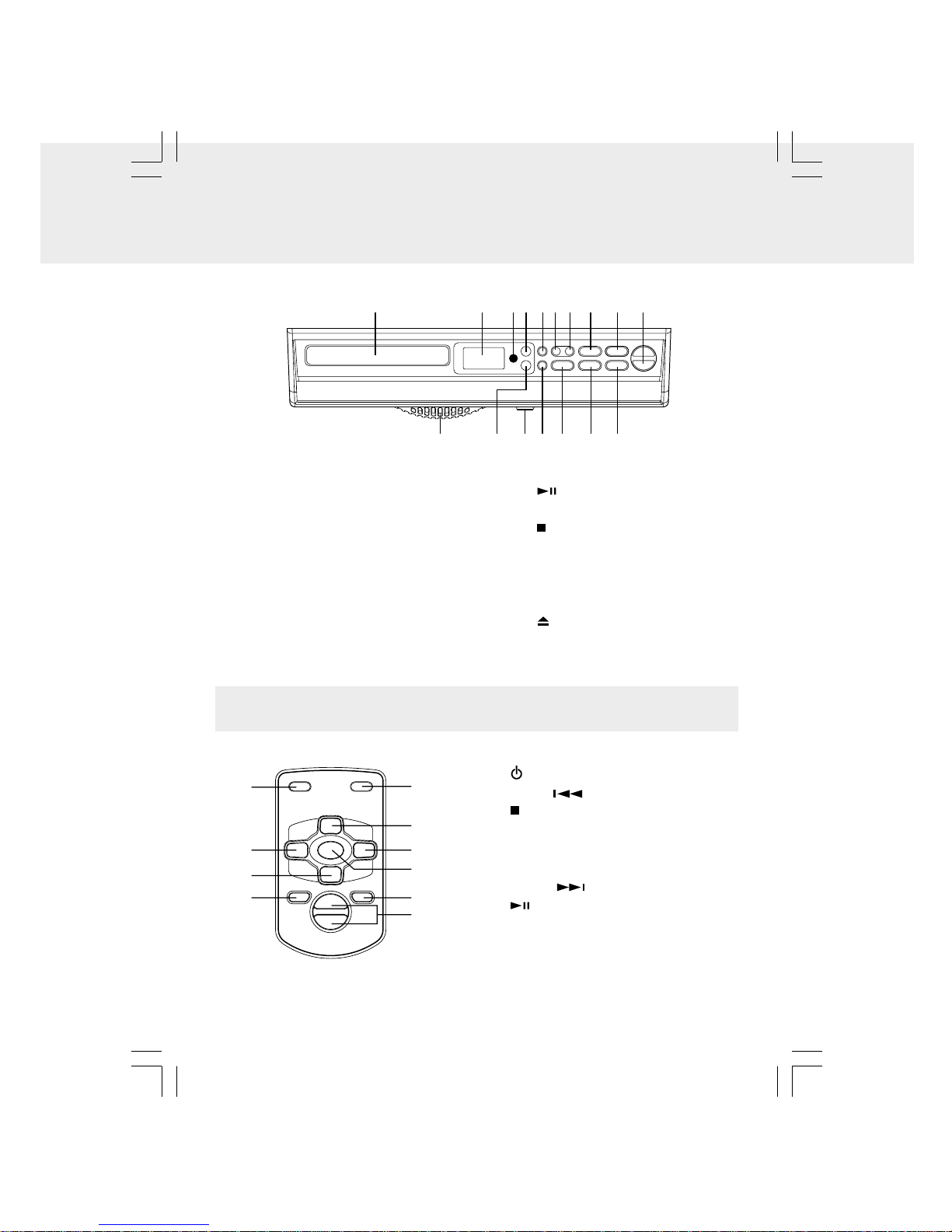
Figure 8
Spacers
Cabinet
Overhang
Equaltoor
Longer than
Cabinet
Overhang
Cabinet
Bottom
38
/”Minimum
g) Gently tighten each screw until they
are firmly holding the unit in place. The
top front edge of the unit should clear
the overhang. Go to STEP4.
- 9 -
FRONTPANELCONTROLS
1234 56789
11
1213
14
15
16
17
10
1. CD Drawer
2. LCD Display
3. Remote Control Sensor
4. POWER (ON/STANDBY) button
5. REPEAT/PRESET button
6. CLOCK SET/MEMORY button
7. TIMER/ON/OFF ·SET button
8. TUNING ·SKIP/TIMER +button
9. PLAY/PAUSE button
10. VOLUME+/-button
11. STOP/BAND button
12. TUNING ·SKIP/TIMER -button
13. CD ·RADIO FUNCTION button
14. DISP (Display) button
15. LIGHT ON/OFF switch
16. OPEN/CLOSE button
17. Countertop Light
REMOTECONTROL
1. POWER button
2. TUN-• SEARCH button
3. STOP/BAND button
4. MEMORY/CLOCK SET button
5. FUNCTION button
6. REPEAT/PRESET+ button
7. TUN+• SEARCH button
8. PLAY/PAUSE button
9. DISPLAY button
10. VOLUME+/-buttons
1
2
3
4
5
7
8
9
10
6
Tabla de contenidos
Otros manuales de Radio reloj de Audiovox

Audiovox
Audiovox CE609CR Manual de usuario

Audiovox
Audiovox CD1120 Manual de usuario

Audiovox
Audiovox RP5640 Manual de usuario

Audiovox
Audiovox CR8030iE5 Manual de usuario

Audiovox
Audiovox Portable MP3 CD Player Manual de usuario

Audiovox
Audiovox CR-308 Manual técnico

Audiovox
Audiovox CE90 Manual de usuario

Audiovox
Audiovox CE255 Manual de usuario

Audiovox
Audiovox CE200 Manual de usuario

Audiovox
Audiovox RC105 Manual de usuario


