AstroLink 4 micro Manual de usuario

AstroLink 4 micro - astrojolo.com
AstroLink 4 micro
astrojolo.com 2023
WARNING!
Do not connect or disconnect the stepper motor when the power is on.
It may damage the stepper motor controller.
Before changing the stepper motor type make sure
the stepper holding current is set to 0%.
1

AstroLink 4 micro - astrojolo.com
Main features
● can be stacked with 7-port USB 3.0 hub model Y-3184
● focusing motor controller compatible with Moonlite,Robofocus motors, or any generic unipolar or bipolar
stepper motor
● 1/8 and 1/32 microstepping control with 2.0A maximum current and 1.4A maximum continuous hold current
● advanced temperature compensation with scripting support and compensation calculator
● permanent focuser position – no need to park focuser after the session
● 2 adjustable PWM power outputs to control dew heaters, telescope fans, or custom Peltier coolers. The
maximum load is 40W per output
● 3 switchable power outputs to power mount, cameras, or filter wheels. The maximum load is 5A per output
● 2 additional permanent power outputs - one dedicated to the USB hub (Y-3184 type recommended)
● XT60 high current input voltage socket
● temperature/humidity/sky temperature sensors to monitor environmental conditions and calculate the dew
point. It is also used for the automatic control of dew heaters
● sky brightness sensor available
● monitor voltage, current consumption, and total energy consumed during the session – useful when
working in the field with a battery
● user-defined alerts for voltages, current, energy, and temperature changes conditions
● programmable overcurrent and overvoltage protection
● dedicated AstroLink 4 panel software, ASCOM drivers available (Focuser, Switch, Observing Conditions,
Safety Monitor), INDI driver available
Technical data
● dimensions: 155x50x25mm
● weight:115g
● the maximum current drawn from all outputs: 10A
● AstroLink power consumption: 2W max
● regulated PWM outputs: 40W max
● permanent 12V DC outputs: 5A max
● switchable 12V DC outputs: 5A max
● focuser stepper motor outputs: RJ12 6 pin, 2.0A max
● sensor input: RJ11 4 pin I2C digital interface
● auxiliary input: RJ11 4-pin input
2

AstroLink 4 micro - astrojolo.com
Device overview
PWM outputs
AstroLink 4 micro has two RCA outputs that provide PWM (pulse width modulation) regulated voltage. Regulations
cover the full 0-100% range. These outputs are usually used for powering dew cap heaters. Output can be
regulated using both controls in the dedicated panel software and 3rd party software that supports the ASCOM
Switch interface or INDI interface.
Switchable 12V DC outputs
The device contains three switchable DC outputs that may provide a supply voltage for imaging setup components
(camera, mount, etc.). Output can be switched using both controls in the dedicated panel software and 3rd party
software that supports the ASCOM Switch interface or INDI interface.
Focusing motors control
The focusing motor can be controlled with AstroLink 4 micro. The output receptacle is 6 pins RJ12 socket. It
supports 12V unipolar motors with gearboxes and bipolar motors at 1/8 and 1/32 microstepping. The focusing
motor can be controlled with dedicated panel software and via ASCOM Focuser or INDI interfaces.
Permanent 12V DC outputs
These outputs are connected directly to the input 12V XT60 socket (via internal fuse and power monitor). Can be
used to provide power to a mini PC, USB hub, or other device powered with 12V.
Sensors
AstroLink 4 micro has two equivalent sensor inputs, so you can plug any available sensor into any socket and it will
be recognized and properly assigned. Connecting more than one sensor (additional sky temperature and/or sky
brightness) requires an additional sensor signal splitter. Sensor readings are available in the dedicated panel
software and via ASCOM Observing Conditions and INDI interfaces.
WARNING!
Do not connect or disconnect the stepper motor when the power is on.
It may damage the stepper motor controller.
Before changing the stepper motor type make sure
the stepper holding current is set to 0%.
3
AstroLink 4 micro - astrojolo.com
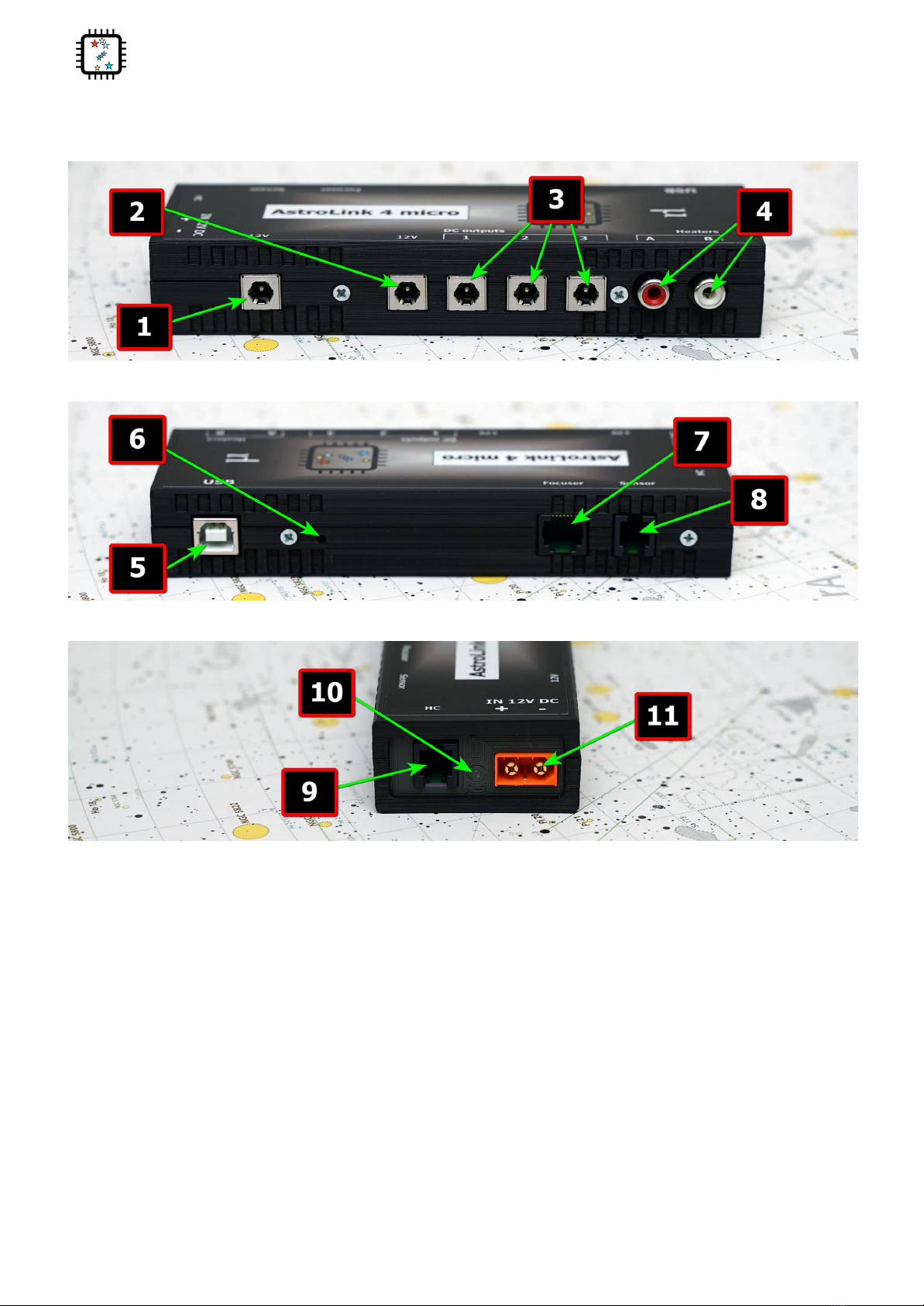
External view
1. permanent 12V DC output (dedicated for Y-3184 USB 3.0 hub)
2. permanent 12V DC output
3. switchable 12V DC outputs
4. 0-100% regulated heaters outputs
5. USB 2.0 input
6. firmware update button
7. focuser motor output
8. sensors input
9. AUX input (hand controller)
10. power LED
11. 12V DC input
4

AstroLink 4 micro - astrojolo.com
There are four M3 threaded holes in the AstroLink 4 micro device bottom. These holes can be used to attach
mounting plates or brackets to the device. Holes separation is 80x20mm.
WARNING!
Mounting screws cannot go deeper than 5mm to the AstroLink 4 micro enclosure.
Using longer screws may damage the device!
5

AstroLink 4 micro - astrojolo.com
USB hub connection
AstroLink 4 micro is designed to work together with USB3.0 hub model Y-3184. The external dimensions of this 7
port USB hub and AstroLink 4 micro are the same, and the power and USB receptacles are aligned, so the hub and
AstroLink 4 micro can be stacked into one device.
The hub may be added by the customer or can be ordered together with the AstroLink 4 micro device. In this latter
case, AstroLink 4 micro and hub are connected permanently, and also there is a DC power connector and short
USB cable included in the set.
6

AstroLink 4 micro - astrojolo.com
Software panel overview
AstroLink 4 micro panel contains several control sections. Most of the area is occupied by different controller
sections, which will be described later on. Below the control section, several other controls are available.
Stay on top checkbox makes the AstroLink panel not go to the background when another application is selected.
Buzzer checkbox controls buzzer activity.
Menu
A small cogwheel menu contains shortcuts to all other settings menu windows, so they can be also opened from
here. There is one additional position in this menu:
●Manual control. You need to check this field when you have connected the manual control box to the
AstroLink device
●Compensation calculator. This option opens an additional popup window with the compensation calculator.
See the Compensation calculator section for details
●Reset device to factory defaults - this option will reset all device settings to factory default values. The
confirmation window will be opened.
●Settings Load.../ Save... - these options allow us to save or load all device settings and configurations. All
settings, labels, initial PWM, and power output values can be stored.
Status bar
The status bar displays several different pieces of information that are visible depending on the context. It is a
read-only field.
7

AstroLink 4 micro - astrojolo.com
Charts and notes
Notes panel - after clicking on this button a small editor will pop up, where you can note down some information
you need during the imaging session (like focuser positions, flat images exposure time, etc.). Its content is saved
dynamically.
Charts button opens an additional window with AstroLink charts. See the AstroLink charts section for details.
Logo icon
After clicking on the logo icon a small information window will pop up. It contains information about firmware and
software versions.
Connection controls
The panel communicates with the device via the ASCOM driver. After clicking on that button a popup window
opens, where all applicable ASCOM drivers are listed and you need to select the proper one.
After choosing the desired driver and clicking OK the actual driver setup window opens, where you need to select
the serial port where the device is connected and other parameters. You may also test the selected serial port if the
communication to the device is correct.
After that, you may connect to the device using the Connect button.
8

AstroLink 4 micro - astrojolo.com
There are two more tabs available for the ASCOM driver. There you can adjust sky temperature cloud coverage
mapping points that correspond to clear sky and maximum cloud coverage, and set names for DC and PWM
outputs that will be visible in ASCOM Switch client software.
Connection status
Small indicator field with selected driver and light. Gray means not connected, green means connected, and red
means active communication.
9

AstroLink 4 micro - astrojolo.com
Focuser section
The focuser position in mm is calculated based on the focuser position in steps and step size defined
in settings.
The coarse relative movement factor can be set in settings between 2 and 10.
The motor status icon may be in three colors: red means the motor is rotating, yellow means the motor is idle but
holding current is applied, and green means idle and no holding current is applied.
Temperature compensation and focuser settings are described below.
Max. focuser position - here you need to enter the maximum focuser position, so the focuser will not
move to any larger value. This is to prevent any mechanical damage to the focuser.
Step size [um] - this value is stored in the driver and can be provided to any 3rd party software when
requested. It is not used internally in AstroLink.
Reversed - you can check this box when selecting the proper behavior of the focuser, so decreasing the
focuser position will cause the focuser tube to move into the telescope
10
Tabla de contenidos


