Ariterm Biomatic+ 20 Manual de usuario

• Ariterm Biomatic+ 20
ARITERM-VTT-S-07229-11.1
INSTALLATION AND OPERATING
INSTRUCTIONS

ARITERM SWEDEN AB • ARITERM OY • Asennus ja käyttöohje • Installation och driftanvisning • Installation and operating instruction • UK 25.05.2012 • 2/32
ARITERM-VTT-S-07229-11.1
Ariterm Biomatic+ is a cost-effective, resistant and environmentally friendly combination of
a central heating boiler and a pellet burner intended for use for the heating of single-family
detached houses and the production of hot domestic water using pellets. Additional/back-
up heat is produced by an incorporated electrical resistance (9 kW). Standard equipment
includes an automatic convection cleaning system and an automatic heating circuit regulation
system. Detailed technical data can be found on page 3. To make use of all features of the
boiler and burner, it is important to observe these instructions.
Keep this manual in a safe place for future reference. Read this manual carefully before start-
ing to use your Ariterm Biomatic+ pellet heating centre. e power of the pellet burner de-
pends on how many pellets can be fed into and burned in the burner head during one hour.
(is means burning of wood pellets of the usual kind, which approximately comply with
the fuel specifications described in this manual.)
Please note! Follow the recommendations contained in this manual when using and servicing
the burner and the boiler.
TRANSPORT, STORAGE AND PACKAGE OPENING
Receipt and acceptance
e boiler is delivered in a wooden frame. e base is a platform from which the boiler can
be safely lifted. e package should be unwrapped as close to the installation site as possible.
e factory has insured the boiler against damage during transport from the factory to the
first intermediate storage site. It is important for the person who receives the boiler to verify
the state of the boiler before its acceptance. In case of damage, the dealer must be contacted
without delay.
Storage
e boiler can be stored outside under a rain cover for a short period of time. However, the
preferred option is to store it inside.
Package opening
After opening the package, open the hatch and check the accessory list to make sure that all
loose accessories are contained in the package (cleaning brush handles are attached to the
package).
Disposing of the package
e plastic cover is landfill waste and the boards can be burned.
TABLE OF CONTENTS GENERAL INFORMATION
General information ....................................................................................2
Transport, storage and unpacking..............................................................2
Technical data...............................................................................................3
Functional description .................................................................................4
Safety and alarms .........................................................................................4
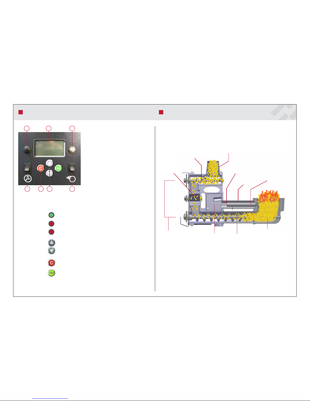
Control panel ................................................................................................ 5
Burner operating principle ..........................................................................5
Boiler installations .......................................................................................6
Pipe installations .......................................................................................... 7
Wiring diagram ............................................................................................ 8
Start-up and stop .........................................................................................9
Burner settings ...........................................................................................10
Burner parts ................................................................................................10
Menu structure .....................................................................................11-14
Heating circuit settings .............................................................................15
Heat regulation examples..........................................................................16
Heat Regulation menu structure .............................................................16
Regulating unit installation and use ........................................................17
Lambda sensor ...........................................................................................17
Alarms and troubleshooting ...............................................................18-19
Decommissioning ......................................................................................20
Most common spare parts.........................................................................20
Service and maintenance .....................................................................21-23
Wood pellets as fuel ...................................................................................24
Feeding system ...........................................................................................25
Declaration of conformity .........................................................................26
Installation record ......................................................................................27
Notes ...................................................................................................28-31

ARITERM SWEDEN AB • ARITERM OY • Asennus ja käyttöohje • Installation och driftanvisning • Installation and operating instruction • UK 25.05.2012 • 3/32
ARITERM-VTT-S-07229-11.1
TECHNICAL DATA
Performance
Power with pellets
Power with oil (different burner)
Combustion efficiency
8-20 kW
20 kW
91%
Dimensions
Dimensions (width x depth x height)
Empty weight
Water volume
601 x 944 x 1,509 mm
245 kg
140 l
Design and adjustment values
Working pressure: boiler
Working pressure: heat exchanger
Working temperature
Recommended underpressure in the combusti-
on chamber
Production of hot tap water
0.5-1.5 bar
max 10 bar
max 120 oC
min 18 Pa, max 25 Pa
1-shower ( 12 l/min), 520 l/+40 C )
2-shower ( 20 l/min, 240 l/+40 C )
Connections
Additional heating circuit unit
Domestic water
Expansion
Discharge
Flue pipe connection
Recommended flue pipe diameter and length
DN 25 male
Cu Ø 22 mm
DN 25 male
DN 15 female
Ø 102 mm
Ø 100 mm steel pipe or equivalent,
length min 4 m
Electrical values | burner side
Power supply
Supply cable
Fuse size
Power in operation
Power in connection
400 V, 3-phase, 50 Hz
9 kW resistance, MMJ 5x2.5s
9 kW resistance, 3x16 A
Burner, ignition 500 W
Burner, normal 40 W
9 kW resistance about 10 kW (depending on equipment)
TECHNICAL DATA ARITERM BIOMATIC+
Standard delivery
• Four-way mixing valve ESBE TM 20
• Sweeping gear
• Dirt trap
• Brick support
• Flue duct joint
• Shunt motor ESBE ARA661 3-point
SPDT 230Vac 6Nm 120s
• Outdoor temperature sensor
• Indoor temperature sensor
• Supply water temperature sensor
• Automatic convection cleaning system
• Flow switch
• Flue gas fan
1. Discharge valve DN 15, female
2. Flue duct Ø 102 mm
3. Additional heating circuit unit DN 25, male
4. Expansion unit DN 25, male
5a. Heating circuit four-way mixing valve supply
5b. Heating circuit four-way mixing valve return
6. Cold domestic water 22 mm Cu
7. Hot domestic water 22 mm Cu
8. Electrical connections
9. Cleanout hatch
10. Ash box
11. Return DN 25, female
12. Display / keyboard
13. Convection sweeper
14. Flue gas blower
Accessory
• Combined flue duct
• Oxygen measurement (Z19014)
• Heating circuit 2
• Unit for interior temperature (14101)

ARITERM SWEDEN AB • ARITERM OY • Asennus ja käyttöohje • Installation och driftanvisning • Installation and operating instruction • UK 25.05.2012 • 4/32
ARITERM-VTT-S-07229-11.1
FUNCTIONAL DESCRIPTION
Heating with the Ariterm Biomatic+ pellet heating centre is similar to oil heating in many
ways. e main difference is that heating with solid fuel produces a certain amount of ash,
which must be removed at certain intervals. If the ash is not removed, combustion efficiency
will decrease and the burner may malfunction.
e BeQuem pellet burner is equipped with automatic ignition. However, it can also be ignited
manually when necessary. e electric ignition system of the burner will only be activated dur-
ing cold starts, i.e., when the system has been inactive for a long period and the boiler tem-
perature has dropped to at least 8°C below the target temperature. During the heating process,
the necessary ignition cycles take place by means of the embers in the burner head. is saves
electric energy.
e burner and the incorporated feeding
system operate automatically. e opera-
tion of the burner is controlled by the tem-
perature sensor installed in the boiler. e
burner head contains an accurately defined
mixture of fuel and air, which ensures per-
fect combustion which is both cost-effective
and environmentally friendly.
e auger burner is over-pressurised dur-
ing operation. e purpose of this is to re-
duce the risk of damage to the burner if the
draught is weak.
Wood pellets with a diameter of 6 or 8 mil-
limetres (not in combination) are the recom-
mended fuel for the boiler.
Ash is removed from the ash box located in
the lower part of the boiler. Ash can also be
removed into a special ash pan by means of
an ash trap or a common vacuum cleaner.
However, the ash may still be hot. erefore,
the ash trap must be heat-resistant.
Standard equipment includes an automatic
heat regulation system that adjusts the sup-
ply water temperature according to the tem-
perature outside.
For safety reasons, the pellet heating centre and fuel store must be placed apart from each other
to prevent possible damage. Any malfunctions or damages caused by incorrect handling will
then be limited to the burner. e fuel store must be built as a separate, fire-classified, confined
space.
Faults that cause the system to stop are indicated by a red indicator light. In addition to this, a
text message appears on the display indicating the cause of the fault.
During every operating cycle, a small amount of pellets (150 g) is fed from the pellet store via
the external feeding system to the upper connection of the burner. To make it possible to dis-
pense an accurate and equal amount of pellets during every cycle, the dispensing is carried out
by means of a separate feeding auger via the blocking feeder and auger burner to the burner
head.
As the auger burner feeds pellets forward three times faster than they arrive at the auger, a safe-
ty zone, containing only single pellets, is created between the burner head and the upper con-
nection. is safety zone always remains intact even in the event of power failure, insufficient
maintenance or equipment breakage.
Alarms are described in "Troubleshooting".
SAFETY AND ALARMS
The feeding auger must be installed in such a way
that its position with respect to the drop funnel
enables the drop pipe to hang free outside the
burner should a re occur in the back.

ARITERM SWEDEN AB • ARITERM OY • Asennus ja käyttöohje • Installation och driftanvisning • Installation and operating instruction • UK 25.05.2012 • 5/32
1 5
2 4
7 6
3
ARITERM-VTT-S-07229-11.1
Dispening auger
Blocking feeder
Upper connection
Primary air pipe
Ignition pipe
Auger Burner
Fan
Pellets are fed
to the burner head from
below
(underfeeding principle)
Safety zone
against fire
in the back
Ignition resistance
BURNER OPERATING PRINCIPLE
Green: The burner is on
Red: Alarm (the burner is off)
Blinking light: Warning light (do not turn the burner off)
Arrow keys: browsing menus / changing setting
C button: exiting menus / acknowledging warnings / ac-
knowledgement of setting
Enter button: selecting settings / go to sub-menu
1. Inner circulation pump switch
2. Inner circulation pump fuse
3. Display
4. Over heating sensor
5. Main switch
6. Operation and alarm indication by
means of an indicator light
7. Operation button
Temperature
Boiler 80(80)°C
Flue gas -40°C
Burner off (on)
Auger, external
Manual operation off
CONTROL PANEL

ARITERM SWEDEN AB • ARITERM OY • Asennus ja käyttöohje • Installation och driftanvisning • Installation and operating instruction • UK 25.05.2012 • 6/32
ARITERM-VTT-S-07229-11.1
Pipe installations
Before installing the boiler, the heating network must be flushed and checked by means of a
water-pressure test. After installation, make sure that all joints are tight. e factory is not
responsible for damages caused by leaking joints.
Dirt trap and manometer installation
It is recommended that the dirt trap delivered with the boiler be installed in the cold water
pipe before the heat exchanger. ere is no manometer in the boiler. erefore, it must be
installed in the heating network.
Safety valve installation
e valve must be CE marked. Its maximum opening pressure must be 1.5 bar and its mini-
mum size DN 15. e safety valve must be chosen according to the highest pressure class of
the combination of devices. Devices that can close the connection must not be installed be-
tween the valve and the boiler. e blowdown pipe must be dimensioned and installed in such
a way that it does not limit the valve blowdown efficiency and does not cause dangerous situa-
tions during the operation of the valve.
Electrical installations
A pellet burner, a 9 kW electrical resistance and an internal circulation pump with its switches
are installed in the boiler and are ready for use. e boiler contains an overheat protection for
the burner and the electrical resistance. e electrical installations related to the boiler must
be carried out by an installer with the relevant qualifications. e connection is carried out ac-
cording to the enclosed connection diagram. A safety/maintenance switch must be installed in
the voltage supply system of the boiler.
Before commissioning
Before starting the boiler, the following should be checked:
• the heating network and the boiler are full of water (pressure at least 0.5 bar).
• air is removed from the internal circulation pump through the venting screw located in the
pump head.
• the flue damper (if any) is open.
• the circulation damper located in the convection part of the boiler is in place.
• the circulation pump is running.
• the network valves are open.
• the ventilation air intake is open.
• the safety valve is in working order and there are no obstacles between it and the boiler.
BOILER INSTALLATIONS
Flue pipe connection and ventilation air intake
Recommended flue pipe diameter Ø 100 mm
Flue pipe length 4 m
Recommended underpressure* in the combustion chamber 8-15 Pa
Ventilation air intake 100 cm2
e boiler should be installed by a company with the proper professional qualifications. e
installation must always be carried out in accordance with, at the time being, valid local stand-
ards and regulations.
NOTE!
All electrical connections must be carried out by a professionally-qualied electrician.
Space requirement
e boiler room must always meet, at the time being, valid local standards and regulations. At
least one meter of free space is recommended to be left in front of the boiler for cleaning and
maintenance operations. It is also recommended to leave about 80 cm of free space on the other
side and at least 50 cm above the boiler.
NOTE!
The boiler must located be at a distance of no less than 180 mm from the back wall. In addition, it
must be possible to remove the ue gas fan whenever maintenance requires it.
Flue pipe connection and combustion air intake
Silicon sealant with a temperature resistance of 350°C can be used as a sealing compound for
joints. e flue pipe must be made of steel or equivalent material. e flue pipe length must
be dimensioned according to the building requirements. e ventilation air intake must not be
covered.
BOILER INSTALLATIONS
* Measure the vacuum in the measurement hole on the left-hand side of the burner. Slacken off
the black screw.
NOTE! The vacuum in the chimney is not critical because the boiler is equipped with a suction fan.
However, it must be dimensioned to be able to evacuate the ue gases without overpressure oc-
curring as the ue gases could then leak into the building.

ARITERM SWEDEN AB • ARITERM OY • Asennus ja käyttöohje • Installation och driftanvisning • Installation and operating instruction • UK 25.05.2012 • 7/32
VV
KV
TV
ARITERM-VTT-S-07229-11.1
1. ARITERM BIOMATIC+
2. 4-WAY VALVE, FLOOR HEATING (RADIATOR HEATING)
3. CONNECTION SET OF THE ADDITIONAL HEATING CIRCUIT
(RADIATOR HEATING)
4. HEAT PIPE PUMP, FLOOR HEATING
5. HEAT PIPE PUMP, RADIATOR HEATING
6. FLOOR HEATING NETWORK MANIFOLDS
7. RADIATOR HEATING NETWORK
8. EXPANSION VESSEL
9. SERVICE SHUT-OFF VALVE
10. SAFETY VALVE
11. FILLING VALVE
12. FEED MIXING VALVE
13. DOMESTIC WATER CIRCULATION PUMP
PIPE INSTALLATIONS
VW
CW
DW

ARITERM SWEDEN AB • ARITERM OY • Asennus ja käyttöohje • Installation och driftanvisning • Installation and operating instruction • UK 25.05.2012 • 8/32
ARITERM-VTT-S-07229-11.1
WIRING DIAGRAM

ARITERM SWEDEN AB • ARITERM OY • Asennus ja käyttöohje • Installation och driftanvisning • Installation and operating instruction • UK 25.05.2012 • 9/32
ARITERM-VTT-S-07229-11.1
Burner start-up and stop
Turn the burner and the internal pump on from the operating switch. If the flow switch that
controls the internal pump is on, set the operating switch to Off mode. The main menu, which
shows the temperatures of boiler water and flue gases, will appear on the display. The main
menu also shows the Start-up/Stop setting and mode of the burner. If the buttons are not
pressed for 10 seconds, a graphic showing temperature and burner data will appear on the dis-
play.
The first start-up differs from normal start-up in that there are no pellets in the burner. Like-
wise, there are no pellets in the external feeding system.
Carry out the following actions in connection with the first start-up or if there are no more pel-
lets in the store:
1. Turn the external auger on from the main menu and wait until pellets arrive at the upper
connection of the burner The external auger will automatically stop after 15 min (the set-
ting can be changed).
2. Set the burner to ON mode.
Cold start
The burner performs a cold start by means of the ignition resistance when the boiler wa-
ter temperature is more than 8°C below the set value. The Burner setting shows the message
"Start-up 1K", the auger burner turns on and so does the red indicator light. Shortly after-
wards, the blower and the ignition resistance turn on. A cold start consists of seven phases
(1K-7K). When the flame detection system detects a flame in the burner head, the burner
moves directly to phase 5K and the green indicator light turns on. When starting directly from
phase 7K, the burner stops for 10 minutes in order for the combustion process to normalise in
the burner head. If the flame does not ignite after phase 7K, the burner gives a cold start alarm
as described in "Troubleshooting".
Do not change the settings during a cold start. After cleaning the burner head, make sure that
the burner performs a cold start because there are no embers in the burner head. The success
of the cold start can be ensured by sufficiently increasing the set boiler water temperature and
by changing it back to the desired value after ignition.
Hot start
e burner performs a hot start when the boiler water temperature is within 8°C of the set
temperature, for example, after a short power failure. During a hot start, the burner uses the
embers in the burner head for ignition and, by doing so, saves energy. In normal use, when the
burner goes from Maintain mode to Power mode, the burner performs a hot start. e burner
starts up automatically after power failures (hot or cold start depending on the temperature of
boiler water).
START-UP AND STOP
Power mode - Maintain mode
After ignition, the burner starts using the Max power range. When the boiler water tempera-
ture rises to within 4 ºC of its set value, the burner starts using the Mean power range and
will continue to use it until the set value is reached. When the target boiler water temperature
is reached, the burner blower still runs for one minute before the burner moves to Maintain
mode (heating method off ). While the burner is in Maintain mode, the auger burner brings
pellets to the burner head every now and then in order to maintain the embers. (Setting “Em-
ber maintenance”)
Stop
e burner can be stopped at any stage of the combustion process. Set Burner to Off in the
main menu. e blower will continue to function for one minute after the burner has been
stopped.
Use as accumulator
As an option an Accumulator tank sensor can be connected to the boiler, an addition to which
a charging pump (a load pump) can also be controlled. e load pump is to be connected to
connectors 14 and 15 (230 vac) and the tank sensor to connectors 63 and 64.
e Load pump-setting is taken in to use from the Accessories-menu. is will automatically
put the Holding time setting to off-mode. e burner’s starting- and stopping temperatures
can now be set. ese are controlled by the tank sensor. Load pump’s starting temperature is
set by the Load pump diff-setting. When the boiler temperature exceeds the Set tempera-
ture - Load pump diff-setting, the pump will start. When the tank has warmed and the burner
stopped, the pump will go off when the boiler water temperature has dropped by 2 degrees
from the set temperature.

ARITERM SWEDEN AB • ARITERM OY • Asennus ja käyttöohje • Installation och driftanvisning • Installation and operating instruction • UK 25.05.2012 • 10/32
1
11
8
62
5
9
7
3
4
10
12
ARITERM-VTT-S-07229-11.1
1. Combustion vessel
2. Flame detection system
3. Level switch, receiver
4. Upper connection
5. Level switch, transmitter
6. Blower
7. Auger burner
8. Blocking feeder
9. Drive motor
10. Wheels and chain (not in the figure)
11. Primary air pipe
12. Connector panel
BURNER PARTS
e settings for combustion and burner operation can be found in the Power menu.
Combustion adjustment
In most cases, the factory settings are sufficient for proper and efficient combustion. In addi-
tion, they can be applied when the underpressure in the combustion chamber is about 8-15 Pa
and the pellets used have a diameter of 8 mm. In connection with commissioning, it is recom-
mended that the values be adjusted by a skilled installer by means of a flue gas analyser. Carbon
monoxide (CO) should be less than 200 ppm and excess air (02) 6.5-8%.
If combustion is poor, the smoke coming from the chimney is black or if the ash produced is
granular, adjust the ratio of fuel to air from the Power menu. Pellet feeding to the burner head
can be adjusted through the High auger and Low Auger settings. e amount of air required
for combustion can be adjusted through the High Fan and Low Fan settings. e Min settings
are not available.
Adjustment example - External auger operating time
e level switches located in the upper connection of the burner measure the amount of pellet
fuel in the burner and control the external storage auger. When the pellet surface drops below
the level switches, the external auger activates (factory setting 30 s). e operating time of the
external auger should be long enough for the pellet surface to rise to the level of the burner up-
per connection. Time can be adjusted from Auger External in the Power menu. If the time is
too long, the pellets rise to the drop pipe level. In this case, pellets may accumulate in the pipe,
which would cause the Pellet Shortage alarm to be given. If the time is too short, there is not
enough time to bring pellets. As a consequence, the same alarm may be given.
Electrical resistance operation
Electrical resistances can be activated from the Burner Adjustments menu. If a 9 kW resistance
is used, set the setting to 3. In this case, 9 kW will be reached in stages (3 kW -> 6 kW -> 9
kW). If the fuse is not sufficient for 9 kW, the setting should be 2, where only 6 kW is avail-
able.
e Activation Start Backup El setting is used to determine how much the boiler water tem-
perature must decrease with respect to the set temperature before the electrical resistances turn
on (Heating method: pellets + electricity). If the burner has malfunctioned or stopped, the
electrical resistance functions as a source of backup heat. If heat is set to be produced only by
means of electricity, the electrical resistance tries to keep the boiler water at the set tempera-
ture.
For example, if the temperature difference of the electrical resistance is set to 20 ºC, the electri-
cal resistance turns on at 58 ºC as long as the set boiler water temperature is 80 ºC. After heat-
ing the water to 62 ºC, the electrical resistance turns off. Settings: Heating method: pellets +
electricity and El step = 1
BURNER SETTINGS
Otros manuales para Biomatic+ 20
2
Tabla de contenidos
Otros manuales de Caldera de Ariterm

Ariterm
Ariterm BioComp-series Instrucciones de instalación y funcionamiento

Ariterm
Ariterm Vedo Instrucciones de instalación y funcionamiento

Ariterm
Ariterm Biomatic 50 Instrucciones de instalación y funcionamiento

Ariterm
Ariterm KMP Uno Manual de instrucciones

Ariterm
Ariterm Bionet+ 12 Instrucciones de instalación y funcionamiento

Ariterm
Ariterm 35+ Manual de usuario

Ariterm
Ariterm Biomatic+ 20i/40 Manual de usuario

Ariterm
Ariterm Biomatic+ Manual de usuario

Ariterm
Ariterm Vedo Instrucciones de instalación y funcionamiento

Ariterm
Ariterm Biomatic 20 Instrucciones de instalación y funcionamiento


