ARH SmartCAM Manual de usuario

Page 1/14
SmartCAM Install Guide

Page 2/14
SmartCAM Install Guide
Document version: 2017.02.09
Table of Contents
INSTALL THE HARDWARE................................................................................................................................................ 3
1. MOUNTING................................................................................................................................................................. 4
2. BRACKET DETAILS AND SIZES............................................................................................................................ 4
CABLE LAYOUTS................................................................................................................................................................... 5
SOFTWARE REQUIREMENTS........................................................................................................................................... 7
ACCESSING THE CAMERA ............................................................................................................................................... 8
RECOMMENDED CAMERA POSITION........................................................................................................................ 9
MAINTENANCE / STORAGE..........................................................................................................................................11
PC RECOVERY MODE ......................................................................................................................................................12
APPENDIX..............................................................................................................................................................................13
CONTACT INFORMATION .............................................................................................................................................14

Page 3/14
SmartCAM Install Guide
INSTALL THE HARDWARE
ADJUST THE BRACKET
1. Loosen the camera fastening screw on the bottom of the bracket. (Use size 5 Allen key).
2. Adjust the bracket into the desired position.
3. Tighten the screw back.
Remove protective film from the protecting plate (on the camera front) before using the
device.
Do not overtighten the screws.
Camera fastening screw

Page 4/14
SmartCAM Install Guide
1. MOUNTING
The bracket can be mounted onto different surfaces. Use appropriate screws for installation
according to the mountable surface.
2. BRACKET DETAILS AND SIZES
Failures due to inappropriate installation void the warranty.

Page 5/14
SmartCAM Install Guide
CABLE LAYOUTS
POWER CABLE
ETHERNET CABLE
The lower two connectors of the back panel of the camera are for the power supply and Ethernet
connection.
The additional two sealed outputs are designed for GPS and radar connections if necessary.
ETHERNET SPECIFICATION: CAT5e crossover cable with RJ45 plug.
The layout of the upper user I/O connector is the following:
INDICATION
USER I/O CABLE
FRONT VIEW (CAMERA CONNECTOR SIDE)
K
OPTO1_IN_S
J
OPTO1_IN_G
T
OPTO1_OUT_S
H
OPTO1_OUT_G
M
OPTO2_IN_S
N
OPTO2_IN_G
A
OPTO2_OUT_S
P
OPTO2_OUT_G
B
RB_USER
R
TA_USER
C
GND_USER

Page 6/14
SmartCAM Install Guide
Route the cable according to the image
to avoid collecting rainwater at the socket.
POWER SPECIFICATIONS:
Please consider voltage drop if you use cables.
AC INPUT
isolated 24-28V AC
POWER CONSUMPTION
14W (max. 33W with heating)
INPUT CURRENT
(WITHOUT HEATING)
0.6A
(max. 2.5A transients occur for a few msecs)
OVER-CURRENT
PROTECTION
by fuse
TRIGGER SPECIFICATIONS:
Input: min. 5V, max. 12V Logic Output: min. 5V, max. 12V, max. 10mA
Pulse width: min. 1 ms
Be aware of the polarity.

Page 7/14
SmartCAM Install Guide
SOFTWARE REQUIREMENTS
The SmartCAM is developed to operate without any kind of special software.
SOFTWARE REQUIREMENTS:
For network setup, administrator (root) privileges are necessary.
Web browser: Mozilla Firefox 47, Internet Explorer 10-11, Google Chrome 51 or later
editions. If it is possible, update your browser (Firefox or Chrome) to the newest available
version.
To enable all camera functions, enable JavaScript and ActiveX controls in your browser.
Page 8/14
SmartCAM Install Guide
ACCESSING THE CAMERA
STEPS OF ACCESSING THE WEB INTERFACE OF THE CAMERA FROM A BROWSER:
1. Connect the camera to a computer or network switch, then power on the camera. After it is
turned on, both status LEDs (red and green on the camera front) are turned on while the
camera is booting. After finished, the green status LED flashes two times while the red one
turns off signaling that the camera is ready for operation.
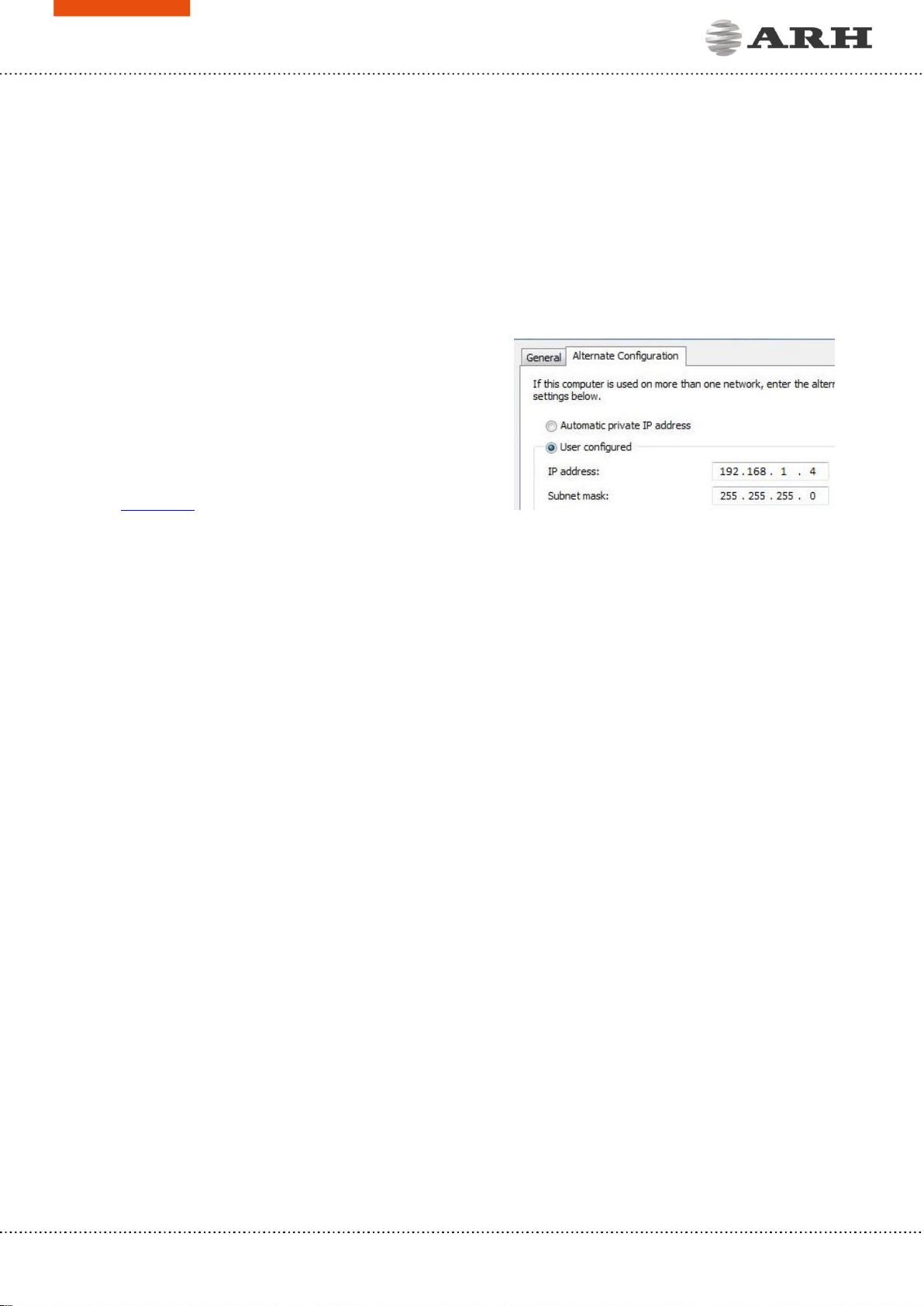
2. Enter an alternate IP address (or set your
computer’s IP) in the 192.168.1.x subnet –where
x is an integer number between 1 and 254
except 3 –with the subnet mask of
255.255.255.0. For more information, see
Appendix.
3. Use the ping command to test the communication with the camera:
Windows: C:\>ping -t 192.168.1.4
Linux: username@mylinux:~$ ping 192.168.1.4
4. Soon, the ping package returns: Reply from 192.168.1.4. If not:
ofirst check the Ethernet LEDs at the PC or the switch side
ocheck whether the IP address is set correctly; the own IP address of the PC can
be pinged.
oproxy is set in the browser or the browser is not set to offline.
If these obstacles are checked and there is still no reply, power off then on and enter the
previous ping command again.
5. Start a browser then enter the default IP address of the camera into the address bar
(http://192.168.1.4). After this, the camera starts with administrator privileges, ready to be
set up and configured.

Page 9/14
SmartCAM Install Guide
RECOMMENDED CAMERA POSITION
A good ANPR engine can read the plates from images taken in various conditions. However, if
you want to achieve over 95% recognition rate with short recognition times, you have to calculate
the position of the camera accurately. The best position is if the camera is installed on gentry
above the traffic lane (see below).
If there is no possibility to install a gentry above the concerned road section the installation of
the camera can be done near the road. In this case the angle between the camera axis and the
direction of the vehicle movement should be minimal and the camera should be installed 1 –
1,5 meters above the headlights of the vehicles.
The distance between the camera and plate is also important. If the camera is too far from the
plate, the characters may not be large enough for recognizing them. In this case, zoom-in until
you reach the proper size. If the distance is too short it may happen that a part of the plate is
over the camera’s field of view (when the vehicle is near to the side of the lane or the plate is
not at the middle of the vehicle).
From the point of ANPR/LPR the most important is the size of the characters on the image. For
English characters it is recommended to have at least 16 pixel average character height, for
Arabic or other special characters it is recommended to have 20 pixel height (due to they are
more calligraphic than the English characters). The too large characters are also not suitable for
ANPR, therefore try to avoid settings where the character size is greater than 50 pixels in height.
A line width of a character on the image should be at least 2 pixels.

Page 10/14
SmartCAM Install Guide
A properly set camera should provide a similar image:
A proper sample image
Proper character sizes (in pixels) on the sample image
Tabla de contenidos
Otros manuales de Cámara digital de ARH


