Argus Security SW-SKT-01 Manual de usuario
SW-SKT-01
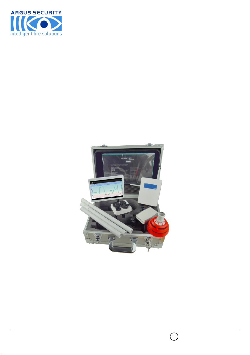
Sagittarius Wireless Survey Kit c/w Tablet
User Manual
ARGUS SECURITY S.R.L. - Via del Canneto, 14 - 34015 - Muggia (TS) - Italy www.argussecurity.it
1
General description
To ensure that a wireless fire detection system works correctly and to avoid installation issues, the use of the SW-SKT-01 is strongly recom-
mended, as it is a proven test kit that enables the installer to check the wireless link quality on the installation site and therefore choose the
perfect position for the wireless devices.
The SW-SKT-01 is a “ready to use” diagnostic system; it’s easy to use and it doesn’t need a particular programming setup.
When the kit’s tablet is remotely connected to the SGWE expander module through the Dongle interface device, the wireless link quality is
shown on the tablet’s dedicated app.
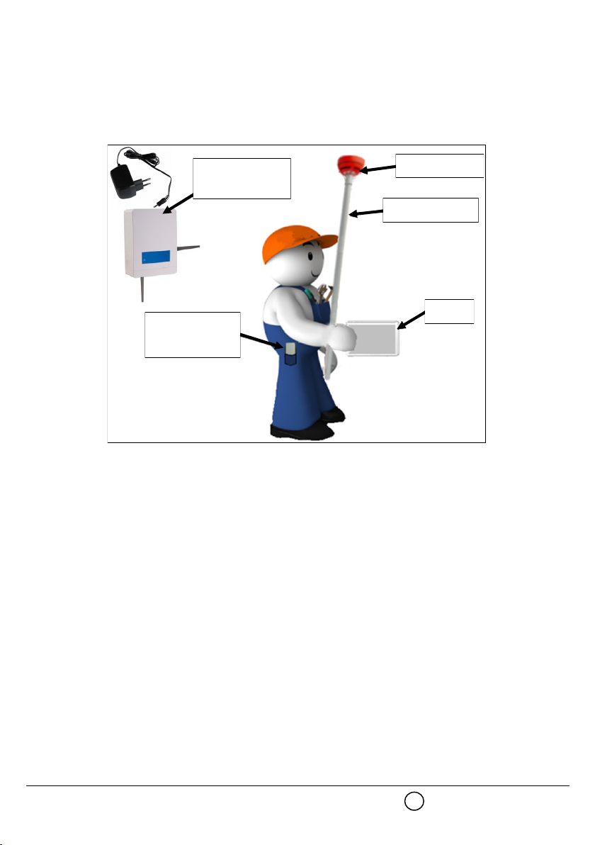
The installer can easily move around the site with the tablet, the Dongle and the survey detector to check the quality signal level between the
SGWE and the survey detector (picture 1).
SW-SKT-01 kit’s content list
- 1x SGWE test expander
- 1x SGWE’s power supplier (12 Vdc)
- 1x SGWE’s battery connector cable
- 1x wireless detector survey probe
- 1x survey detector’s supporting pole (3x sub-assembly parts)
- 1x Dongle interface device
- 1x tablet
- 2x CR123A (3Vdc)
- 2x LR6 AA (1.5 Vdc)
- 3x screws
- user manual
Wireless expander
Test detector
Supporting pole
Tablet
Dongle interface
device
Picture 1
2
Technical specifications
ARGUS SECURITY S.R.L. - Via del Canneto, 14 - 34015 - Muggia (TS) - Italy www.argussecurity.it
SGWE test expander
Available operating frequen-
cies 868 / 865 / 916 / 434 MHz
Number of available radio
channels
7 channels
6 channels for the 434 MHz band
Maximum radiated power
5 dBm (3 mW)
10 dBm (10 mW) for the 434
MHz band
Power supply voltage range 9 Vdc - 30 Vdc
Current load 30 mA at 12 Vdc
Operative environmental
temperature range -30 °C - +50 °C
Weight 300 g
Dimensions (with antennas) 190 mm x 230 mm x 50 mm
Dimensions
(without antennas) 120 mm x 160 mm x 50 mm
IP IP 51C
SGWE mains power supplier
Output voltage 12 Vdc
Output current load 420 mA
Output connector type 5.5 x 2.1 x 12 mm DC Jack
Input voltage range 90 Vac - 264 Vac
Input current 0.25 A (100 Vac)
Input frequency 63 Hz
Input protection Internal T1.0A/250 Vac fuse
Weight 80 g
Dimensions 37.0 x 55.1 x 42.9 mm
Survey wireless detector probe
Available operating frequen-
cies 868 / 865 / 916 / 434 MHz
Number of available radio
channels
7 channels
6 channels for the 434 MHz band
Maximum radiated power ≤ 14 dBm (25 mW)
Power supply batteries type 2x CR123A (3 Vdc)
IP 40
Operative environmental
temperature range From –10 °C to +55 °C
Colour Orange fluorescent
Dimensions 110 mm x 65 mm
Weight 190 g
Dongle interface device
Available operating frequen-
cies 868 / 865 / 916 / 434 MHz
Number of available radio
channels
7 channels
6 channels for the 434 MHz
band
Maximum radiated power ≤ 14 dBm (25 mW)
Power supply batteries type 2x LR6 AA (1.5 Vdc)
USB connector characteristics
for external power supply 5 Vdc, 100 mA
IP 40
Operative environmental
temperature range From -10 °C to +50 °C
Dimensions 118 mm x 79 mm x 19 mm
Weight 90 g
3
Specifications for the SGWE power supply battery
Suggested output voltage
range 12 Vdc - 24 Vdc
Measure of the wireless link quality
Wireless link quality between devices can be measured using two indicators:
dB units
Simply decibel units.
RSSI units
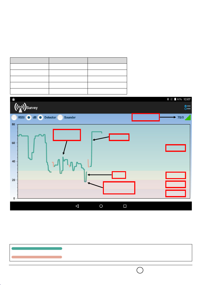
RSSI is the acronym of “Radio Signal Strength Indicator” and it is obtained from the measure of the wireless signal quality (in dB units) and the
noise level (still in dB units). In order to simplify the measurement of the wireless signal’s quality, RSSI and dB units are spaced out in five
possible “mark” levels (table 1); on the tablet’s survey app, levels from Mark 5 to 2 are visualized using four different colours (picture 2); Mark
1 is considered as “no link”.
In order to work properly, the devices must operate with a signal level quality in the Mark 5 (picture 2, green area) or Mark 4 (picture 2, yellow
area) bands.
Mark 3 band is not recommended.
If the signal’s level quality is below Mark 3 (i.e. Mark 2), you must change the position of the devices (either the SGWE or the survey probe
detector).
If the SGWE and the probe detector do not communicate, the survey app will show a warning popup.
You will notice that the signal’s value graph on the survey app is traced either in green or, sometimes, in orange:
Mark level dB units RSSI units
Mark 5 More than 30 dB More than 20 RSSI
Mark 4 From 20 to 30 dB From 13.4 to 20 RSSI
Mark 3 From 10 to 20 dB From 6.8 to 13.4 RSSI
Mark 2 From 0 to 10 dB From 0 to 6.8 RSSI
Mark 1 Less than 0 dB Less than 0 RSSI Table 1
Excellent
Good
Not recommended
Mark 5
Mark 4
Mark 3
Mark 2
Signal’s value
Picture 2
Signal’s value
graph
Green colour indicates that the wireless signals are received on the SGWE primary antenna.
Orange colour indicates that the wireless signals are received on the SGWE secondary antenna.
4
Survey setup
SGWE test expander
1. Place the SGWE test expander in the exact location of the installation site where you want to install a wireless system central or relay node
(i.e. VW2W100 wire to wireless translator, SGWE wireless expander or a SGCWE100 wireless conventional system expander module).
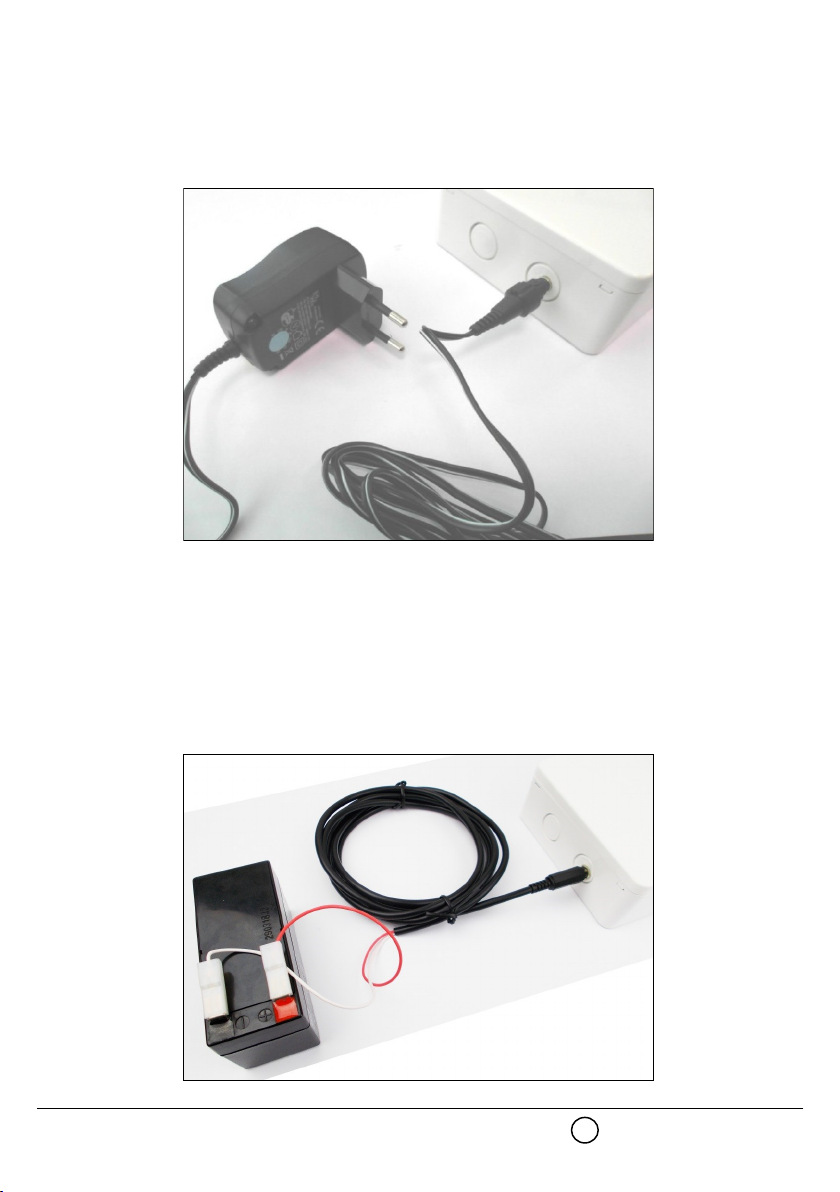
2. Connect the power supplier’s output to the SGWE; the socket for the connector is located on the top side of the SGWE (picture 3a).
3. Connect the power supplier to the household mains line.
Alternatively, you can connect the SGWE test expander to a suitable power supply battery through the battery connector cable (picture 3b).
Battery’s suggested specifications are given at the beginning of this manual.
1. Place the SGWE test expander in the exact location of the installation site where you want to install a wireless system central or relay node
(i.e. VW2W100 wire to wireless translator, SGWE wireless expander or a SGCWE100 wireless conventional system expander module).
2. Connect the red wire push-on terminal to the battery’s positive pole.
3. Connect the white wire’s push-on terminal to the battery’s negative pole.
4. Insert the battery connector’s jack plug into the SGWE power supply socket; this socket is located on the top side of the SGWE.
SGWE is now ready for use.
ARGUS SECURITY S.R.L. - Via del Canneto, 14 - 34015 - Muggia (TS) - Italy www.argussecurity.it
Picture 3a
5
Picture 3b
Survey detector
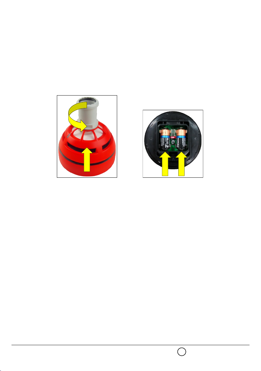
1. By rotating it clockwise, remove the survey detector from its support base (picture 4).
2. Extract the battery cover from the bottom of the detector.
3. Insert both CR123A batteries into their detector’s housing (picture 5).
Batteries polarities must match the indicated polarity on the detector.
4. Wait until the LEDs at the top of the detector stop blinking.
5. Reinstall the detector’s battery cover.
6. Reinstall the detector on its base.
The survey detector is now ready for use.
Picture 4 Picture 5
6

Supporting pole
The supporting pole is used to enable the assessment of the wireless link quality in high locations.
It can be used, also, for assessing lower locations and areas for possible interference caused by wireless fading.
1. Assemble the pole as per picture 6.
2. Fix the survey detector probe at one end of the pole (picture 6).
Dongle interface device - battery power supply
1. Extract the battery cover from the back of the Dongle device.
2. Insert both LR6 AA batteries into their housing.
Batteries polarities must match the indicated polarity on the device.
3. Reinsert the battery cover.
4. Switch on the Dongle device (On / Off switch on the device; check picture 8).
Dongle’s LED performs some green-red blinking, then stops: the device is now powered on.
www.argussecurity.itARGUS SECURITY S.R.L. - Via del Canneto, 14 - 34015 - Muggia (TS) - Italy
Picture 6
Picture 7
LED
OFF ON
Picture 8
7
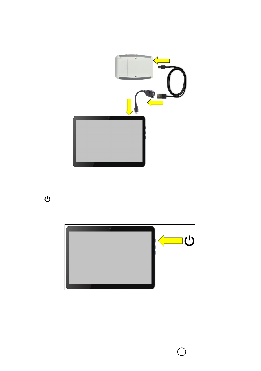
Dongle interface device - external power supply
- Connect the Dongle’s Micro USB with OTG cable (not supplied) port to the tablet’s Micro USB port (picture 9)
or
- connect the Dongle’s Micro USB port to the output of the tablet’s power adapter.
External power supply is useful in the event Dongle’s batteries run out.
Tablet
1. Long press the key on the side of the tablet (picture 10).
Tablet’s “lockscreen” will appear.
2. To access the main screen follow the instructions manual of the tablet.
Picture 9
Picture 10
8
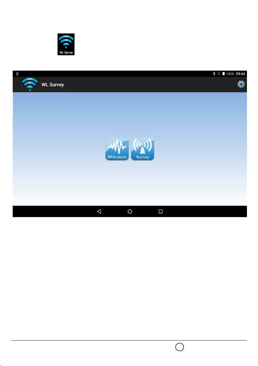
WL Survey
Before start make sure Bluetooth and Gps/Geolocalization are enabled as per tablet’s instruction manual.
1. Tap on the WL Survey icon to start.
Tablet screen appears as follows:
2. Check that RFAnalyze and Survey icons are blue; if they are grey coloured, consult the troubleshooting section at the end of this manual.
3. Tap on one of the icons to start the needed app.
RFAnalyze
This tool is used to monitor wireless environmental traffic in one or more channels; purpose of this is to find a relatively clean channel suitable
for your wireless system.
Interference that can be assessed with this app is normally caused by other wireless devices or other equipment operating within the moni-
tored channel or channels.
Survey
This app is used to measure the wireless signal’s link quality between the test SGWE and the survey probe.
ARGUS SECURITY S.R.L. - Via del Canneto, 14 - 34015 - Muggia (TS) - Italy www.argussecurity.it
Picture 11
9
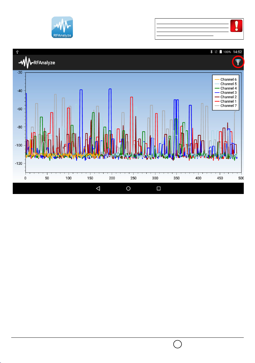
RFAnalyze
Tap on the RFAnalyze icon to start the app.
The following window will appear:
At the beginning, this window shows, through a graph, the degree of wireless traffic present in ALL channels; a single graph of one colour
shows the traffic present in one single channel.
Picture 12
Bear in mind that the analysis of the
channel you are working on is strongly
recommended in order to avoid possible
problems during commissioning.
10
Tabla de contenidos
Otros manuales de Instrumento de medición de Argus Security


Manuales populares de Instrumento de medición de otras marcas


Endress+Hauser
Endress+Hauser Proline Promag 50 Especificaciones técnicas

Siemens
Siemens SITRANS F Coriolis FCT030 Manual de lista de piezas

KLINGER
KLINGER CMF V Series Manual de usuario

EXFO
EXFO FTB-2 Manual de operación y mantenimiento

Keysight
Keysight M8290A Manual de usuario

ADTEK
ADTEK MW-5 Manual de usuario