AquaSource 873-W4801 Manual de usuario
Questions, problems, missing parts? Before returning to your retailer, call our
customer service department at 1-866-417-7564, 8 a.m. - 8 p.m., EST, Monday - Friday.
1
AB12401A
ATTACH YOUR RECEIPT HERE
Serial Number ____________ Purchase Date ____________
Lowes.com
ITEM #0247399
0247086
TUB AND SHOWER
FAUCET
MODEL #873-W4801
873-W4804
Francias / Español p. 14
AquaSource®is a registered trademark of
LF, LLC. All rights reserved.
2
Lowes.com
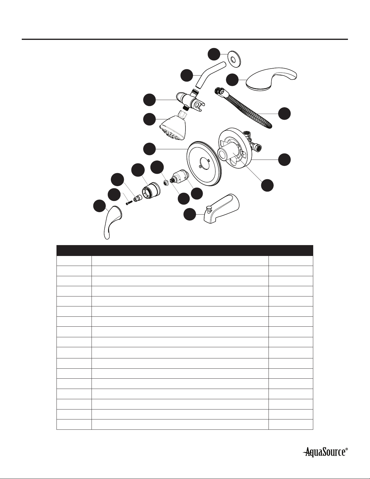
PACKAGE CONTENTS
A
BC
D
E
F
J
G
H
L
I
M
P
OQ
N
K
PART DESCRIPTION QUANTITY
A Shower Flange 1
B Shower Arm 1
C Hand Shower 1
D Diverter 1
E Showerhead 1
F Escutcheon 1
G Valve Body 1
H Hose 1
I Handle 1
J Tub Spout 1
K Inverter (Preassembled to Valve Body (G)) 1
L Sleeve 1
M Cartridge (Preassembled to Valve Body (G)) 1
N Screw (Preassembled to Valve Body (G)) 1
O Bonnet (Preassembled to Valve Body (G)) 1
P Cartridge Stem (Preassembled to Valve Body (G)) 1
Q Stop Ring (Preassembled to Valve Body (G)) 1
3
Lowes.com
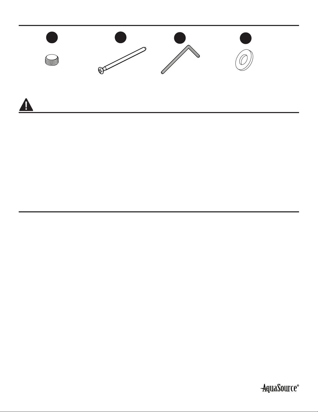
HARDWARE CONTENTS (not shown to actual size)
AA
x1
BB
Escutcheon Screw
x2
CC
Allen Wrench
x1
SAFETY INFORMATION
Please read and understand this entire manual before attempting to assemble, operate, or install the
product.
WARNING:
Follow the installation instructions carefully. Proper installation is the installer’s responsibility.
Failure to follow correct installation procedures can result in the faucet being loose, which can
result in serious injury.
CAUTION:
Check local building codes before beginning installation to ensure compliance.
PREPARATION
Before beginning the assembly of this product, make sure all parts are present. Compare parts with
the package contents and hardware contents list. If any part is missing or damaged, do not attempt to
assemble the product.
Estimated Assembly Time: 180 minutes
Tools Required for Assembly (not included): Adjustable Wrench, Phillips Screwdriver, Sealant Tape,
Pliers, Saw, Goggles
Helpful Tools (not included): Pipe wrench
Plug
DD
Rubber Sealing Washer
x2
4
Lowes.com
ASSEMBLY INSTRUCTIONS
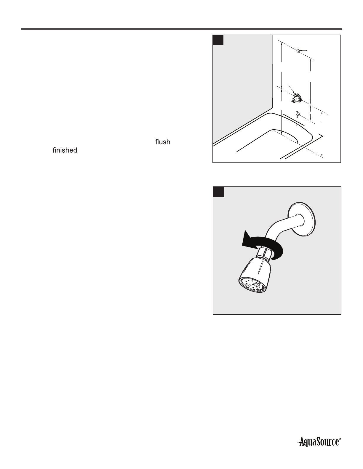
1. Prepare the bath area for installation:
a. Shut off the water supply to the tub and shower.
Note: This may require shutting off the main water
supply to your home.
b. Verify that the hole sizes and positions in the
wall are correct. There are the recommended
component measurements:
– Shower and Spout Outlet Hole: 1-1/4 in.
diameter
– Valve Access Hole: 6 in. diameter
– Recommended Valve Depth to Finished Wall:
2 in. min. to 2-1/2 in. max. Ensure that the
black template plate’s surface is with the
exterior surface of the wall. Position
the valve body correctly in the wall. The 8 in.
minimum from the valve body to the tub spout
is required for proper operation.
1
Tub&Shower
Shower Only
30in.
6in. Dia
48in.
1 1/4in. Dia
1 1/4in. Dia
48in.
Shower Only 8in. Min.
30in.
Tub&Shower
2. Remove existing shower valve. Clear any debris from
the shower and bath area. Clean old sealant from any
threaded connections.
2
5
Lowes.com
ASSEMBLY INSTRUCTIONS
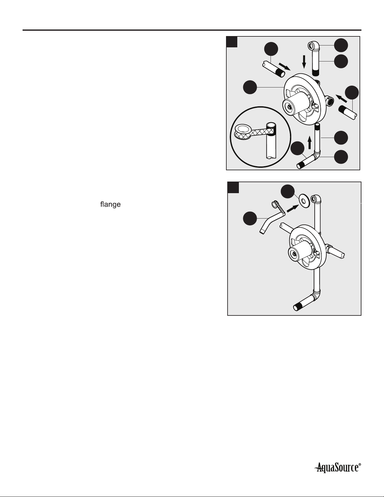
3. Install the valve body (G):
a. Wrap thread sealant tape (not included) around
the pipe threads in a clockwise direction.
b. Connect the hot and cold water supplies (1)
(not included), the shower outlet pipe (2) (not
included), and tub outlet pipe (3) (not included)
by threading them into the valve body (G) in a
clockwise direction. Tighten the pipes to the valve
body with a pipe wrench (not included). Connect
the pipe elbows (4) (not included) to the end of the
shower outlet and tub outlet pipes. Connect the
tub spout outlet pipe (5) (not included) to the lower
pipe elbow (not included). Tighten the elbows
and tub spout outlet pipe connections with a pipe
wrench.
3
G
4
1
1
2
4
3
5
4. Install the shower arm (B):
a. Insert the long end of the shower arm (B) through
the shower arm (A) and wrap thread
sealant tape (not included) to both sides of the
shower arm (B).
b. Thread the long end of the shower arm (B) into the
pipe elbow inside the wall in a clockwise direction.
c. Carefully tighten the shower arm (B) with a
wrench. Do not overtighten as it could do damage
to the shower arm (B).
4
B
A
6
Lowes.com
ASSEMBLY INSTRUCTIONS
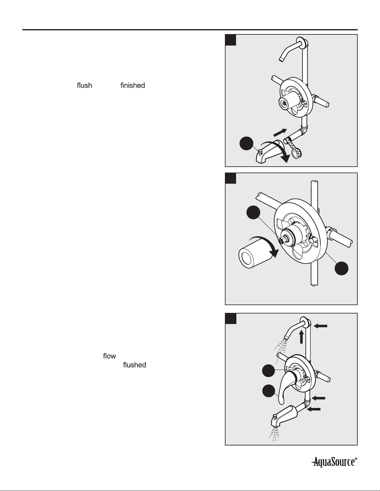
5. Install the tub spout (J):
a. Wrap thread sealant tape around the pipe thread of
the tub spout outlet.
b. Thread the tub spout (J) into the threaded
connection and twist clockwise until the spout
becomes with the wall.
5
J
6. Remove the plastic cap from the valve body (G) by
twisting the cap in a clockwise direction. 6
G
L
7. Check for leaks:
a. Place the handle (I) on the end of the inverter (L)
and turn the handle to the on position.
b. Turn on the hot and cold water supply lines and
allow the water to from the outlets until all
foreign matter has been out of the line. Run
hot and then cold for one minute each.
c. Check for leaks.
d. Shut off the water at the faucet and supply lines.
7
I
L
7
Lowes.com
ASSEMBLY INSTRUCTIONS
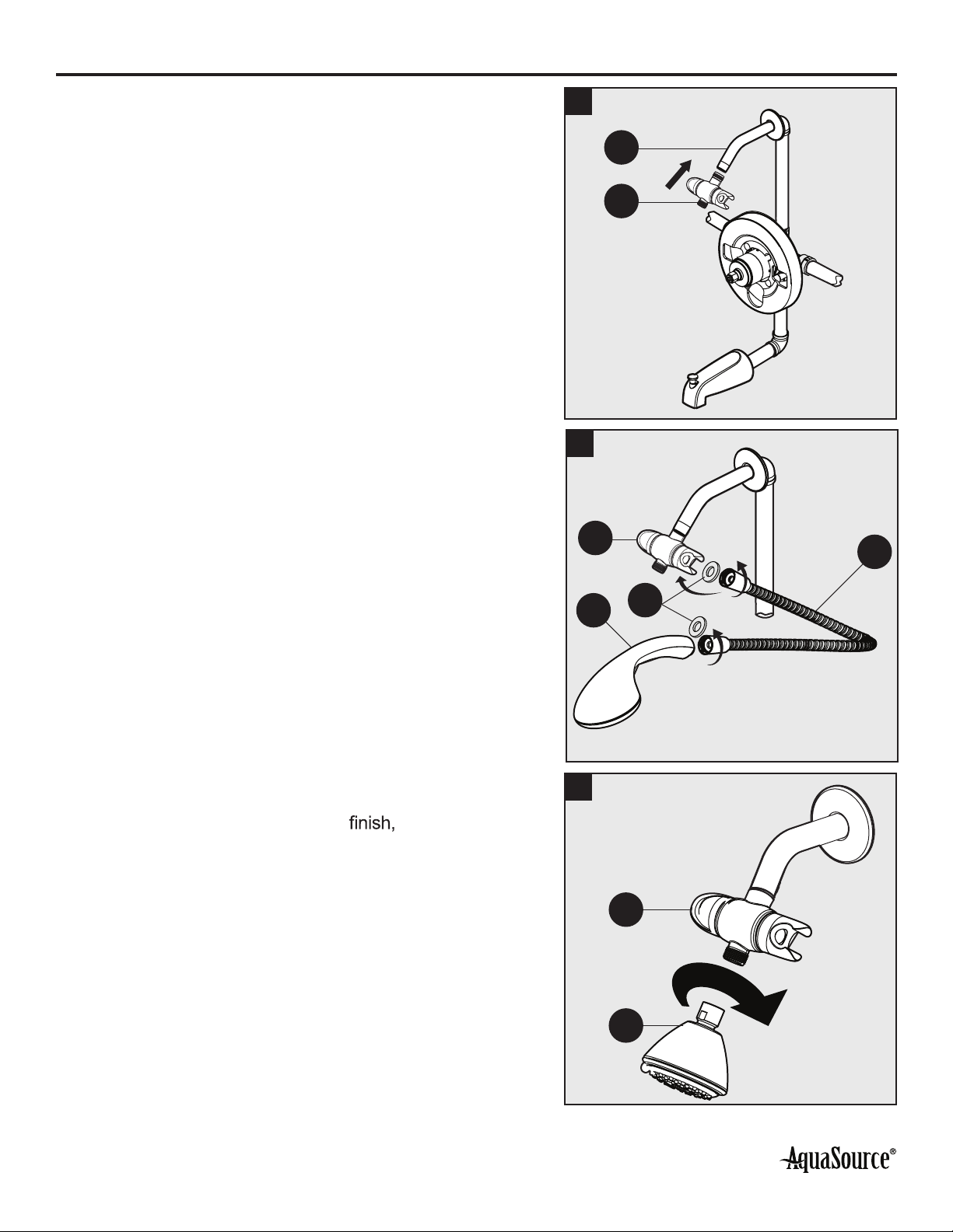
8. Hand-tighten the diverter (D) onto the shower arm (B). 8
D
B
9. Insert one of the rubber sealing washers (DD) into the
end of the hose (H) and hand tighten to the diverter (D)
and the other end of the hose (H) to the hand shower (C).
Hand-tighten all connections.
10. Install the showerhead (E) to the front of the diverter
(D) by twisting in a clockwise direction. Tighten with a
wrench. To avoid damage to the place a cloth
between the wrench and showerhead.
10
E
D
9
D
C
H
DD
8
Lowes.com
ASSEMBLY INSTRUCTIONS
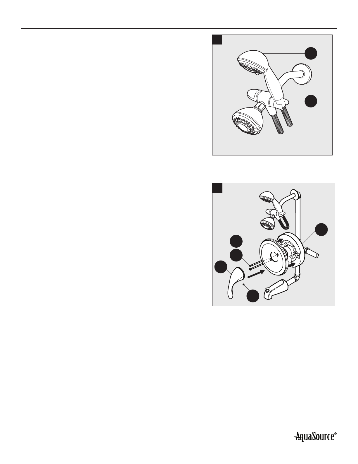
11. Place the hand shower (C) into the holder on the
diverter (D). 11
D
C
12. Install the escutcheon (F) onto the valve body (G) and
secure to the valve body (G) using the escutcheon
screws (BB). Place the handle (I) onto the valve body
(G) and secure with the handle screw (1) using the
Allen wrench (CC).
12
F
G
BB
I
1
9
Lowes.com
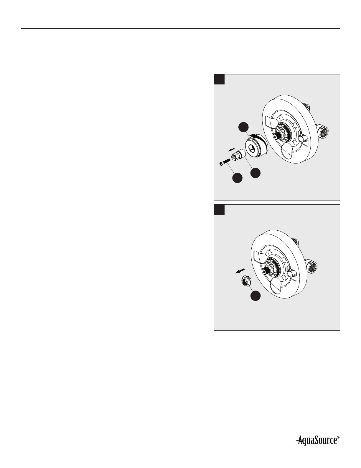
ADJUSTING THE TEMPERATURE LIMITER AND WATER FLOW ON THE VALVE
The limiter on the valve can be set to allow partial or full access to hot water by limiting how far the
handle can be turned to the hot side of the valve. The limiter is typically set at the factory to allow only
warm water to pass through the valve. Follow the directions in this section if you wish to adjust the
amount of hot water that is allowed through the valve.
1. Unscrew the screw (N) using a Phillips screwdriver (not
included) and remove the inverter (K). Then unscrew
the sleeve (L).
1
NK
L
2. Remove the red limit stop ring (Q). 2
Q
10
Lowes.com
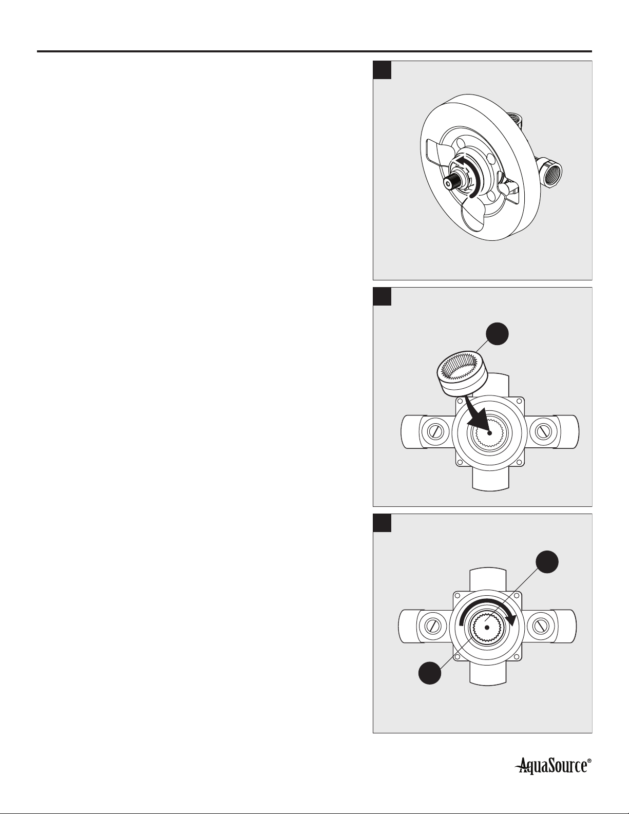
ADJUSTING THE TEMPERATURE LIMITER AND WATER FLOW ON THE VALVE
3. Slowly turn the valve stem counterclockwise to adjust
the desired maximum water temperature. 3
4. Reinstall the red limit stop ring (Q) and readjust the
teeth engagement position so that the stem cannot
move beyond the adjusted point.
4
Q
5. Turn the red limit stop ring (Q) to the right and replace
it on the cartridge stem (P) to change the maximum
amount of hot water allowed through the valve.
Optionally, you can completely remove the limiter (Q)
to allow the maximum amount of hot water through the
valve. This does not affect the performance of the valve.
5
Q
P
Este manual sirve para los siguientes modelos
3
Tabla de contenidos
Otros manuales de Accesorio de baño de AquaSource


