APEC ULTRA REVERSE OSMOSIS SYSTEM Manual de usuario

ULTRA REVERSE OSMOSIS SYSTEM
INSTALLATION INSTRUCTION
Free Drinking Water .com

Please keep this Owner’s Manual for future reference.
It contains useful information on how to maintain and care for your
APEC Reverse Osmosis water filter system.
TABLE OF CONTENT
1. Installation:
Preparation ................................................................... page 1
Filter housings & membrane assembly ............................. page 4
Feed water connection .................................................... page 6
Drain saddle connection ................................................ page 8
Faucet mounting ........................................................... page 9
Connecting the whole system ......................................... page 11

1
Thank you for choosing APEC reverse osmosis sytems.
You now own the finest water filter in America.
Please read and become familiar with instructions and parts needed before proceeding with
the installation.
BEFORE INSTALLATION:
Inspect the system:
Please take the system and all the components out of the box. Inspect the system and all the con-
nection fittings carefully, make sure nothing is damaged during shipping. If any part is cracked or
broken, please do not proceed with the installation and contact APEC or your distributor for an
exchange or diagnosis.
Recommended tools list:
Variable speed drill
Drill bit: ¼” (for the waste line), 1/8” (as pilot, not mandatory), and ½” (for standard
faucet hole, air-gap faucet requires 1&1/4” hole)
5/8”, 9/16” open-end wrench, or adjustable wrench, pliers
Phillips screwdriver
Utility knife, or scissors
Teflon tape
Operating Parameter
Operating pressure: 100psi maximum
Feed water temperature: 40 – 100 degree F (4-37 degree C)
Do not connect this unit to hot water source
Install the RO in a sheltered environment, avoid exposure to hot and cold weather or under
direct sun light.
Copyright:
This manual is copyrighted by APEC Inc. Under the copyright laws, this manual may not be reproduced in any form, in
whole or part, without the prior written consent of APEC Inc.

2
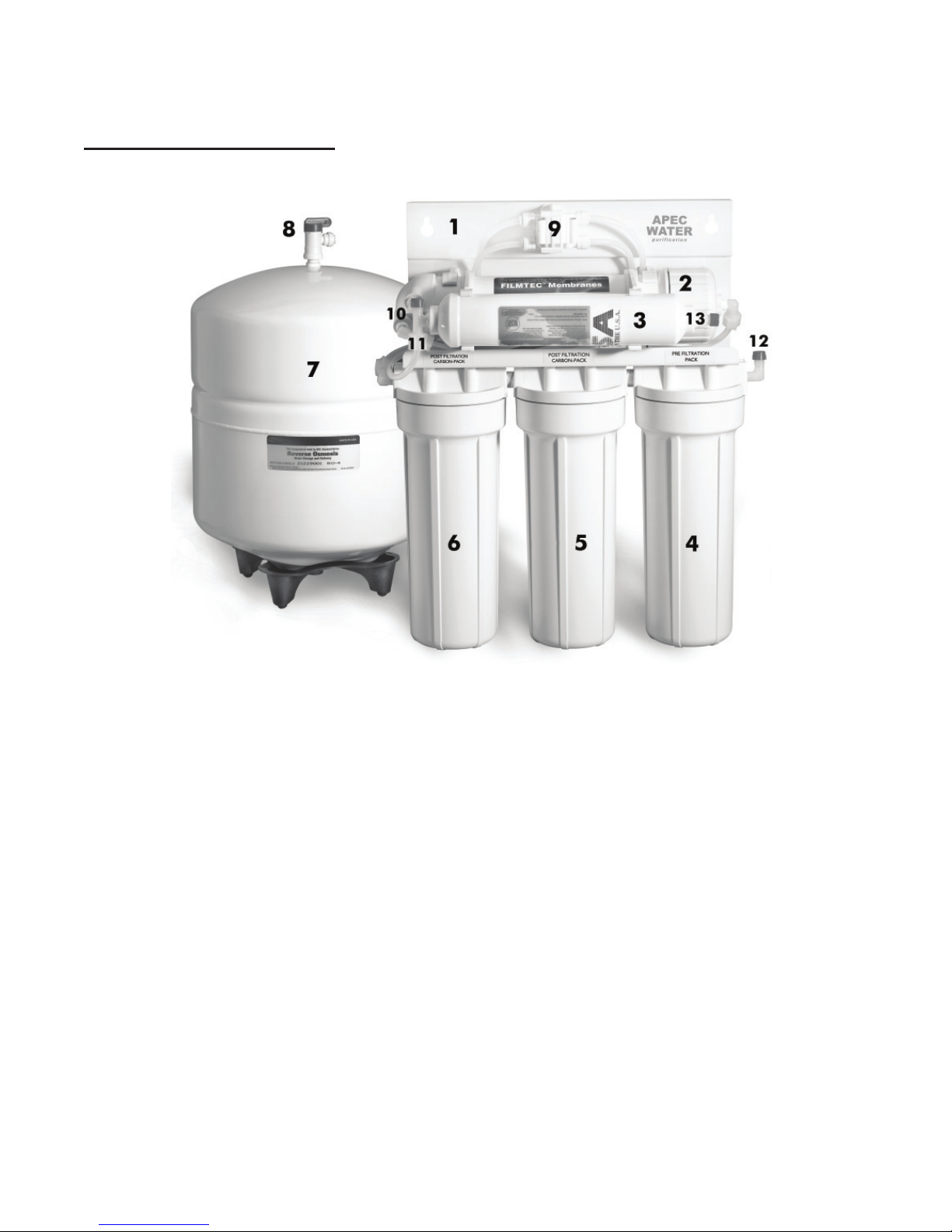
1 RO system head 3 Pre-filters in 3 Housings 1 Storage tank 1 RO Membrane
Installation kit includes:
1 Faucet with 1 Feed water adaptor 1/2” 1 Drain saddle for waste water
washers and nuts with needle valve kit
3 Color tubing 1/4” 1 tank’s ball valve 1 Wrench 3 pairs Plastic nuts
for opening housing and inserts
for standard systems
(1 pair for quick-connect models)
Insert
Plastic Nuts
Components included with the RO system:
Make sure you have all these parts before starting installation.
3
Component Itemization:
1) Bracket
2) Membrane and housing (4th-stage filter)
3) In-line carbon filter (5th-stage filter)
4) Sediment pre-filter and housing (1st-stage filter)
5) Carbon block pre-filter and housing ( 2nd-stage filter)
6) Carbon block pre-filter and housing ( 3rd-stage filter)
7) Storage tank
8) Tank ball valve
9) ASO – Automatic Shut Off valve
10) Check valve (Internal check valve encased in plastic fitting)
11) T-fitting
12) Feed water inlet
13) Product (filtered) water outlet

4
THERE ARE THREE PARTS TO INSTALLING THE RO SYSTEM:
Part I. Assemble the filters and housings onto the main system
Part II. Placing the Membrane into the membrane housing
Part III. Installing the system
PART I. ASSEMBLE THE FILTERS AND HOUSINGS ONTO THE MAIN SYSTEM
Remove plastic/paper wrappings on the 3 filters, put them into the 3 housings, and assemble the
housings onto the main system as follow:
Fig. 1 Stand the 3 housings upright. Make sure each housing has a rubber O-ring in its
groove.
Put the “Puretrex 5 micron” sediment filter into the “1st stage” housing on the right.
Put the “Matrikx +CTO” carbon filter into the “2nd stage” housing in the middle.
Put the “Matrikx +CTO” carbon filter into the “3rd stage” housing on the left.
Fig. 2 Starting from the 3rd stage housing on the left, hand twist the housing onto the main
system turning counterclockwise, one by one, for all 3 housings.
Fig. 3 Use the wrench provided to completely tighten the housing starting from 1st-stage.
Repeat this step for the 2nd stage housing in the middle, and for the 3rd stage hous-
ing on right.
Note: For some people it is easier to use the wrench with the system laid down
(face up).
Fig. 1 Fig. 2 Fig. 3
3rd
Stage
2nd
Stage
1st
Stage
Use
Wrench

5
PART II. PLACING THE MEMBRANE INTO THE MEMBRANE HOUSING
This system has been wet tested in the factory, and the RO membrane is sealed to preserve
freshness.
1. Locate the blue membrane and remove it from the plastic bag.
2. Locate the Membrane Housing (labelled “Membrane” ) on the system.
3. Fig. 4A 1. Disconnect the RED tubing from the membrane housing’s cap. Do so by un-
screwing the plastic nut on the fitting.
2. Remove the membrane housing cap (turn counterclockwise).
3. See Fig 4B. Insert membrane all the way into the housing tightly with the correct
side going in first as shown below.
Note: Make sure the membrane is inserted in the correct way as shown in Fig 4B!
Fig. 4A
Fig. 4B
( Follow these same procedures for future membrane changing and maintenance. )
4. Close the cap of the housing and reconnect tubing as before.
1. First unscrew plastic nut
to take tubing out
2. Unscrew membrane housing
cap (counter clockwise)
3. Insert Membrane

6
PART III. INSTALLING THE SYSTEM
Space: Make sure there is sufficient space under the counter for installation (an area of about
12”Lx6”Wx18”H for the system, 11”diam x18”H for tank).
The RO system is best installed under the kitchen sink. But if that is not feasible you can install the
system anywhere where there is a cold water supply with sufficient water pressure for the chosen
RO model, and an outlet to drain off the waste water from the system.
Mounting: No need to mount the RO system on the wall. The RO system can stand in the sink
cabinet without mounting, this makes future filter change easy and convenient. If you prefer to
mount the system to the wall, please make sure it can be taken down easily for filter replacement.
Step 1: Feed Water Connection
See Fig. 5D: The RO system must be connected to the COLD water supply only!
1. Locate the Cold water supply valve under the kitchen sink (the round or oblong handle on the
right side). Turn off the incoming cold water completely by turning the shut off handle clock-
wise.
Note: If the cold water shut off valve can not turn off the water, the main water supply to the
house must be shut off for the installation. Another option is to use a “self piercing
saddle valve” from APEC or from a local hardware store.
2. Feed Water Adaptor (1/2”): See Fig. 5. The Feed Water Adaptor comes with a separate
Needle Valve. The Adaptor goes inline onto your 1/2” cold water pipe. The Needle Valve por-
tion screws onto the Adaptor as shown in Fig. 5.
The “cone-shaped” washer provided is optional. If your pipe already has a built-in cone washer,
then no need to use this one.
3. For Flex Line Riser: See Fig. 5A. Loosen nut and separate cold water riser tube from faucet
shank. Gently bend riser tube so that the Feed Water Adapter (Fig 5) fits onto the faucet shank.
If your riser tube has no built-in washer, then fit the cone-shaped washer provided onto the riser
tube. Connect the riser tube, the feed water adapter, and faucet shank together and tighten.
For Solid Copper Riser: See Fig. 5B. Follow the same procedure as for flex line. If the cop-
per riser cannot bend, then it’s best to replace it with a flex line riser. Then fit the feed water
adaptor the same way as described above.

7
NEEDLE
VALVE
FLAT WASHER
CONE WASHER (optional)
*Wrap Teon Tape!
Riser
Tube
For Flexible Line
Faucet
Shank
Needle
Valve
Main Water
Supply
Shut-off
Valve
Riser
Tube
For Solid Line
Faucet
Shank
Needle
Valve
Main Water
Supply
Shut-off
Valve
Sink Sink
Fig. 5 Fig. 5A Fig. 5B
Fig. 5C Fig. 5D
4. Needle Valve: See Fig. 5C. Screw the Needle Valve onto the Adapter tightly. Apply 3-4
rounds of Teflon tap onto Needle Valve before attaching it to the Adaptor.
To open needle valve: Turn needle handle counter-clockwise.
To close needle valve: Turn needle handle clockwise.

8
Test for leaks at this point: Close the Needle Valve (turn needle handle clockwise all the
way in to close) Turn ON the cold water supply to the sink faucet. If the Needle Valve or the
Adaptor leaks, check the connection and try applying more Teflon tape or tighten the brass
nut some more to stop the leak.
Step 2: Drain Saddle Installation
Note: To avoid annoying drainage noise, mount drain line as low as possible
on the vertical tailpiece, or on horizontal tailpiece.
There is constant water pressure “packed” inside the RO system which blocks the waste water
from backing-up into the system. So the waste water is “forced-drained”, not “gravity-drained”.
1. See Fig. 6. The drain saddle assembly should be installed above the trap and on the vertical
or horizontal tailpiece . To reduce the drainage noise, mount the drain line as low as possible
above the trap, or on the horizontal tailpiece.
Fig. 6
2. See Fig.7. Mark the position of the hole on the drain pipe and drill a 1/4’’ hole through one
side of the drain pipe . There is a piece of self-adhesive sponge provided. Glue this sponge
to the inside of the saddle, this will cushion any gap between the saddle and the pipe. Make
sure the hole on the sponge is thoroughly punched out, and is aligned to the hole on the
saddle.
Fig.7 Fig.8
MOUNT DRAIN
SADDLE AT
EITHER
LOCATION
Otros manuales para ULTRA REVERSE OSMOSIS SYSTEM
1
Tabla de contenidos
Otros manuales de Sistema de agua de APEC

Manuales populares de Sistema de agua de otras marcas

Spirotech
Spirotech SPIROVENT SUPERIOR S250 Manual de usuario

Culligan
Culligan Aqua-Cleer Aqua-Cleer Advanced Drinking Water... Manual de usuario

A.O. Smith
A.O. Smith Dura-Max AJH - 1000A - P Manual de usuario

Microline
Microline T.F.C.-4 Manual

Eureka Forbes
Eureka Forbes Aquaguard Select Manual de usuario

Cetetherm
Cetetherm AquaEfficiency Manual de usuario


