
AOR AR-210 Manual de usuario

MODEL AR-210
TERMINAL NODE CONTROLLER
OPERATING INSTRUCTIONS
AOR, Ltd.
Radio Communication Products & Systems

AR-210 Manual I
Page 2
FCC NOTICE
This equipment generates, uses and can radiate radio frequency energy and if not installed and
used in accordance with the instruction manual, had cause interference to radio communications.
This equipment has been tested and found to well exceed the limit for a Class A computing device
pursuant to Subpart J of Part 15 of FCC Rules, which are designed to provide reasonable protec-
tion against such interference when operated in a commercial environment. If this equipment does
cause interference to radio or television reception, which you can determine by turning the equip-
ment off and on, try to correct the interference by one or more of the following measures:
Move the computing device away from the receiver being interfered with.
Relocate the computing device with respect to the receiver
Re-orient the receiving antenna.
Plug the computing device into a different AC outlet so that the computing device and receiver
are on different branch circuits.
Disconnect and remove any I/O cables that are not being used.
(Unterminated I/O cables are a potential source of high RF emission levels.)
If you need additional help, consult your dealer or ask for assistance from the manufacturer. You
may also find the following booklet helpful: "How to Identify and Resolve Radio-TV Interference
Problems". This booklet is available from the U.S. Government Printing Office, Washington, D.C.
20402, Stock No. 004-000-00345-4.
AR-210 Operating Instructions
Copyright © 1992, AOR, Ltd. Tokyo Japan
by Toshi T. Totsuka
All Rights Reserved.
Credits
Portions of this manual was copied from the model HK-21 TNC operating manual under the accep-
tance and courtesy of the Heath Company, Benton Harbour, MI., U.S.A.
Portions of this manual was copied from the TAPR TNC-2 operating manual under the acceptance
and courtesy of the Tucson Amateur Packet Radio Corporation.
Trademarks
IBM, PC, XT, AT and PS/2 are registered trade marks of International Business Machines Corporation.
PC DOS is a registered trademark of the International Business Machines Corporation.
Apple and Apple Macintosh are registered trade marks of Apple Computer, Inc.
CompuServe is a registered trademark of CompuServe, Inc.
GEnine is a trademark of General Electric Corporation.
Hayes is a registered trademark of Hayes Microcomputer Products, Inc.
Procomm and Procomm Plus are registered trademarks of Datastorm Technologies, Inc.
Microsoft, MS and MS-DOS are reistered trademarks, and Windows is a trade mark of Microsoft Corporation.
VT-100 is a trade mark of Digital Equipment Corporation.

AR-210 Manual II
Page 3
TABLE OF CONTENTS
INTRODUCTION ............................................................................... 4
SPECIFICATIONS .............................................................................. 5
1. INSTALLATION
Computer Connections ............................................................ 6
Software Requirements .......................................................... 9
Radio Connections ................................................................. 10
Power Source ........................................................................ 12
NiCad Battery ........................................................................ 13
2. OPERATIONAL TESTS AND ADJUSTMENT
Preliminary Tests .................................................................... 14
Adjustments .......................................................................... 14
Audio Level Adjustment .......................................................... 15
PTT Line Adjustment .............................................................. 15
3. OPERATION
General ................................................................................ 16
Terminal Characteristics ........................................................ 18
Getting Started ....................................................................... 18
Operating Modes ................................................................... 21
Flow Control ........................................................................ 22
Display Options .................................................................... 23
Editing Commands ................................................................ 25
Special Operating Configurations ............................................ 25
Packet Timing Functions ......................................................... 28
Monitor Functions .................................................................. 30
Using the Bulletin Board Feature ............................................ 31
4. COMMAND AND MESSAGES
Command List & Command Syntax ....................................... 34
5. IN CASE OF DIFFICULTY ........................................................... 37
APPENDIX – List of Commands and Defaults .................................... 37

AR-210 Manual III
Page 4
INTRODUCTION
The AOR Model AR-210 Terminal Node Controller is designed as a link between your radio trans-
ceiver and a simple data terminal (or personal computer). This Terminal Node Controller (TNC) al-
lows you to operate new computer-based communications mode – "Packet-Radio". You will find
this unit convenient and easy to use.
The most unique and important feature of Packet-Radio transmissions, unlike RTTY, is that they are
virtually error free. Information that you intend to transmit is first made into digital groups, or
packets. Confirmation of correct reception of these packets is then returned to the originating sta-
tion by the destination station. If the originating station does not receive confirmation, it automati-
cally resends the packets until the correct information is confirmed, or the contact is terminated.
A modem (modulator / demodulator) that can operate at very high baud rates is included in the
unit. This results in very short transmissions by each station and allows several stations to use the
frequency at the same time. Also, due to the choice of operating parameters, you are not aware of
the presence of other stations on frequency.
The unit also functions as an automatic repeater. You may use it as an unattended repeater, a bea-
con or a "mailbox" with the appropriate computer and software. You may also use it with a FSK or
AFSK FM station on the VHF and UHF bands.
In addition to your radio equipment, you will need either an ASCII data terminal or a personal
computer that has an RS-232C output and uses a terminal emulator program. Such programs are
widely available for connecting your computer to a modem like the Hayes Smart modem. They are
often used to access CompuServe, GEnine o other computer telephone service.
The demonstration terminal software supplied with the AR-210 package is for the IBM PS/2,
PC/XT/AT and compatible computers.
A 9 pin straight computer cable supplied with the AR-210 is for the IBM AT or compatible comput-
ers, but you may need a different cable and connectors if the supplied cable does not fit your com-
puter.

AR-210 Manual IV
Page 5
SPECIFICATIONS
Processor Z80A, soft-compatible Application Specific Integrated Circuit.
TMPZ84C015BF-6
Memory Backup Lithium battery.
Serial Port RS-232C interface to terminal or computer
Baud rates 300, 600, 1200, 2400, 4800, 9600 and 19200.
The default, or reset, baud rate is 1200.
Commands TAPR TNC-2 up-load compatible.
Modem Port 1200 baud FSK
Protocol AX.25 Level 2, Version 1.1.4TE
Power Requirements External 10 to 13.8 VDC at 200 mA.
(55 mA from internal 4.8 volt 120 mAh NiCad battery.)
Input Level 20 mV to 2 V peak to peak, 18 Ω.
Output Level 0 to 300 mV (variable).
Push-to-talk 30 V maximum at 100 mA
Overall Dimensions 2½" W × 1" H × 1¼" L
Net Weight 3.3 oz.
AOR, Ltd. reserves the right to discontinue products and changes specifications at without incur-
ring any obligation to incorporate new features in products previously sold.

AR-210 Manual 1-1
Page 6
1. INSTALLATION
Before you can perform the "Operational Test and Alignment", which follows in this section, you
will have to properly connect your AR-210 (thereafter called TNC) to a terminal or a computer and
run the proper terminal emulation program.
In addition, you will have to connect the TNC to you radio equipment, read and comply with the
following information that pertains to your situation under "Computer Connections", "Software Re-
quirements" and "Radio Connections".
If you use a computer you will need a terminal emulator or communications program such as Pro-
com, Procomm Plus or accessory terminal program that comes with MS Windows.
A sample terminal program supplied with the TNC can be used for the IBM PS/2, PC, XT, AT and
compatible computers running under MS DOS.
Since these programs allow a computer to operate like a terminal, the following information
will use the term "Computer" to refer to a computer or a terminal.
The TNC communicates with your computer through a serial port using signals that correspond to
the RS-232C standard. Most computers that are available today either incorporate an RS-232C
style serial port, or have one available as an accessory. If you have already been using your com-
puter with an RS-232C modem, you can use this TNC the same way.
COMPUTER CONNECTIONS
Table 1-1 shows the minimum connections that are required between the RS-232 I/O connector on
the rear of the TNC and your computer. These minimum connections do not permit hardware flow
control. DO NOT connect any wires other than pins 1 through 8 and 20 if your computer I/O is a
DB-25 style connector. Pins 17 through 19 and 21 through 25 are reserved for future use.
The supplied cable i for the IBM PS/2, AT and 100 % compatible computers with DB-9S asynchro-
nous communication port (serial port) connector.
You may also consider using a 9-to-25 pin adaptor for connecting to a 25-pin serial port computers
such as the IBM PC, XT and compatibles.
IMPORTANT: Whether you purchase a ready-made cable or make your own, make sure that it
is a SHIELDED cable.
Pin
Signal Name
Description
2
Receive Data
Data from AR-210 to computer
3
Transmit Data
Data from computer to AR-210
5
Signal Ground
Common ground for both data lines
Table 1-1
It is beyond the scope of this manual to show you how to connect your TNC to every brand and
model of computer. It does however, provide you with information for several common computers.
If your particular computer is not listed, you can probably adapt the information that is presented
to suit your needs.

AR-210 Manual 1-2
Page 7
IBM
Table 1-2 and 1-3 shows the proper cable connections for IBM PS/2, AT and compatible computers
using 9-pin serial port. Use a 9-to-25 pin adaptor for connecting IBM PC, XT and compatible com-
puters with a 25-pin serial port.
AR-210
Signal name
9 WAY IBM COMPUTER RS232
2
Receive Data
2
3
Transmit Data
3
5
Signal Ground
5
7
Ready To Send
7
8
Clear To Send
8
Table 1-2
AR-210
Signal name
25 WAY IBM COMPUTER RS232
2
Receive Data
3
3
Transmit Data
2
5
Signal Ground
7
7
Ready To Send
4
8
Clear To Send
5
Table 1-3
APPLE MACINTOSH
Table 1-4 shows the proper cable connections for an Apple Macintosh computer. This computer
uses an RS-422 serial port. It will operate properly with your TNC. Altough Pin 1 is not connected
inside the computer, we recommend that you connect pin 1 to the main ground of the computer.
AR-210
Signal name
APPLE MACINTOSH
1
Carrier Detect
7
2
Receive Data
9
3
Transmit Data
5
4
Data Terminal Ready
6
5
Signal Ground
3
5
Chassis Ground
1
Table 1-4
OTHER COMPUTERS WITH 25-PIN RS-232C PORTS
If your computer has a 25-pin RS-232C port, refer to its manual to determine the transmit data,
receive data and signal ground pins. Follow the manufacturers recommendations for connecting
the serial port to a modem.
AR-210 Manual 1-3
Page 8
Your TNC is configured as Data Communications Equipment (DCE), while most computers are con-
figured as Data Terminal Equipment (DTE). If this is true of your particular computer, you can
probably connect pins 2, 3 and 5 of your TNC to pin 3, 2 and 7 respectively of your computers RS-
232C port.
If your computer is configured as DCE, you will have to cross the wires between pins 2 and 3 of
the TNC. In other words, connect pin 2 of the TNC to pin 2 of he computer and pin 3 of the TNC
to pin 3 of the computer. The signal ground is the same (pin 5 of the TNC to pin 7 of the com-
puter).
Some computers may require that you connect pin 5 of the serial port connector to an appropriate
signal. Others may require connections to pin 8 and 20. You can use the computers output signals
on pin 4 and 6 for this purpose as shown in table 1-5.
AR-210
Signal Name
Computer
2
Transmit Data
3
3
Receive Data
2
5
Signal Ground
1 / 7
Jumper Pin 4 and 5
4 / 5
Jumper Pin 6, 8 and 20
6 / 8 / 20
Table 1-5
OTHER COMPUTERS WITH NONSTANDARD SERIAL PORT
Computers with non standard serial ports must meet the following conditions:
1. The signal levels should be RS-232C compatible. The TNC requires that the voltage levels that
come from the computer be greater than +3 volts in one state and less than 0 volts in the
other state.
2. The polarity of the signals must conform to the RS-232C standard. A lower voltage state must
correspond to a logical "1" and a higher voltage state to a logical "0".
3. The computer must be able to correctly receive a signal which meets the RS-232C specifica-
tion. The TNC supplies signals that meet this specification.
Make or purchase a cable that provides the necessary connections. The serial port common pin
must be connected to the TNCs serial port connector at pin 5. The data line that sends data FROM
the computer must be connected to the TNCs connector at pin 3. The line that your computer uses
to RECEIVE data must be connected to the TNCs connector at pin 2.
If your computer requires any other signals, you must find ways of providing them. The documen-
tation provides with your computer or its accessory serial port should specify any special require-
ments of your particular port.

AR-210 Manual 1-4
Page 9
SOFTWARE REQUIREMENTS
Any software package that enables your computer to act as an ASCII terminal with an ordinary te-
lephone modem should work with your TNC. If you have a program that you have successfully
used with a telephone modem, and you are familiar with its operation, use that same program to
communicate with the TNC.
WINDOWS TERMINAL
The Windows terminal in the Windows version 3.0 or higher will work properly with your TNC. In
the accessory group, chose the Terminal icon.
From the Setting menu, choose Communications, the communications dialog box should appear.
Select the options according to the following list. Then choose the OK button.
Baud Rate
1200
Stop Bits
1
Parity
Even
Flow Control
Xon/Xoff
Connector
COM 1 or COM 2
APPLE MACINTOSH
The MACTERM program will work properly with your TNC. Load this program and set the options
as follows:
Compatibility
Terminal
1200 baud
VT-100
7 bits/character
ANSI
Even parity
UNDERLINE
Handshake Xon/Xoff
US
Modem connection
80 Columns
Telephone port
ON LINE
AUTO REPEAT
RADIO SHACK
The Radio Shack model 100 and 200 has a built-in terminal program in ROM. Set the TELECOM pa-
rameters by typing [F3]57E1ENN[]. Refer to TELECOM Manual supplied with Model or 200 for
further information.
OTHER SOFTWARE FOR TNC
There are some ham radio groups or individuals who wrote some unique software for packet com-
munications. In particular, the Tucson Amateur Packet Radio Corporation (Non-Profit Research and
Development Corporation) where the TNCs original protocol was created, offers a variety of infor-
mation and software for Packet-Radio users. For further information of the TAPR, contact: Tucson
AR-210 Manual 1-5
Page 10
Amateur Packet-Radio - P. O. Box 12925 Tucson, AZ 85732 Phone 602-749-9497, Fax 602-749-
5636. You may find some interesting topics from Packet Status Register, the quarterly newsletter
from TAPR.
SAMPLE TERMINAL SOFTWARE
If you do not own any terminal software, use the sample diskette supplied with the AR-210. This
sample software works under MS-DOS or PC-DOS only. The diskette also contains source code for
a sample terminal program written by the MS QBasic which can be run through the QBasic pro-
gram comes with MS-DOS 5.0
SAMPLE TERMINAL SOFT OPERATING PROCEDURE
1. Turn ON your computer.
2. Insert the diskette into drive (A or B).
3. From the computer prompt, type TERM [].
If you use a Hard Disk, from the C:\ prompt, type A:TERM [].
4. The communication screen should appear.
5. The default parameters are 1200 baud / 7 bits / Even Parity / One stop bit. Hit [P] while hold-
ing [Alt] key. Use the ARROW key to change the parameter.
RADIO CONNECTIONS
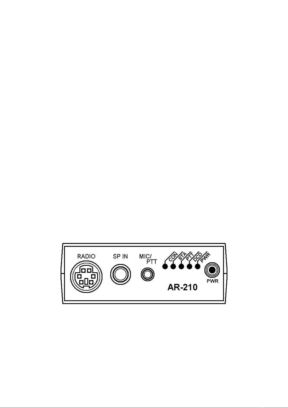
Refer to Figure 1-1 while you read the following information. Depending upon your particular ra-
dio, you can either use the RADIO socket or the SP IN and MIC/PTT sockets. In general, the
RADIO socket is for connection to a base or mobile station and the SP IN and MIC/PTT sockets are
for hand-held transceivers that use a combination audio and PTT cable.
Figure 1-1
AR-210 Front Panel
Tabla de contenidos
Otros manuales de Controladores de AOR


