Ametek Land SYSTEM 4 Manual del propietario
System 4
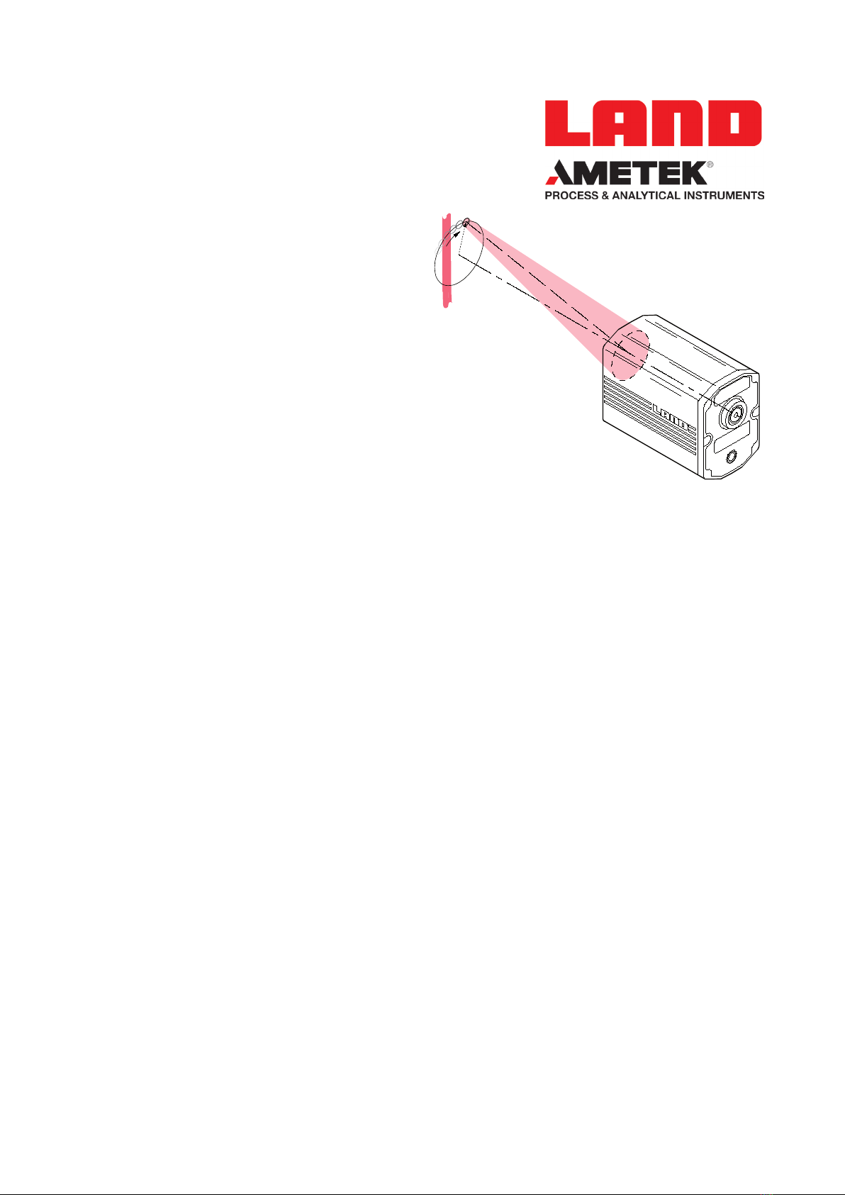
Target Orbiting Thermometer
User Supplement
© Land Instruments International, 2008-2014
Issue 5
28 March 2014
Publication Nº 198.069
Language: English

Health and Safety Information
Read all of the instructions in this booklet - including all the WARNINGS and CAUTIONS
- before using this product. If there is any instruction which you do not understand.
DO NOT USE THE PRODUCT.
Safety Signs
WARNING
Indicates a potentially hazardous situation which, if not avoided, could result in death or
personal injury.
CAUTION
Indicates a potentially hazardous situation which, if not avoided, could result in minor or
moderate injury to the user or users, or result in damage to the product or to property.
NOTE
Indicates a potentially hazardous situation which, if not avoided, could result in damage or the loss of
data.
Equipment Operation
Use of this instrument in a manner not specied by Land Instruments International may be hazardous.
Read and understand the user documentation supplied before installing and operating the equipment.
Protective Clothing, Face and Eye Protection
It is possible that this equipment is to be installed on, or near to, machinery or equipment operating at
high temperatures and high pressures. Suitable protective clothing, along with face and eye protection
must be worn. Refer to the health and safety guidelines for the machinery/equipment before installing
this product. If in doubt, contact Land Instruments International.
Electrical Power Supply
Before working on the electrical connections, all of the electrical power lines to the equipment must
be isolated. All the electrical cables and signal cables must be connected exactly as indicated in these
operating instructions. If in doubt, contact Land Instruments International.
Storage
The instrument should be stored in its packaging, in a dry sheltered area.
Unpacking
Check all packages for external signs of damage. Check the contents against the packing note.
Lifting Instructions
Where items are too heavy to be lifted manually, use suitably rated lifting equipment. Refer to the
Technical Specication for weights. All lifting should be done as stated in local regulations.
IMPORTANT INFORMATION - PLEASE READ
Contact Us
UK - Droneld
Land Instruments International
Tel: +44 (0) 1246 417691
Email: [email protected].uk
Web: www.landinst.com
USA - Pittsburgh
AMETEK Land, Inc.
Tel: +1 412 826 4444
Email: [email protected]
Web: www.ametek-land.com
For further details on all LAND/Ametek ofces, distributors and representatives, please visit
our websites.
Return of Damaged Goods
IMPORTANT If any item has been damaged in transit, this should be reported to the carrier and to the
supplier immediately. Damage caused in transit is the responsibility of the carrier not the supplier.
DO NOT RETURN a damaged instrument to the sender as the carrier will not then consider a claim. Save
the packing with the damaged article for inspection by the carrier.
Return of Goods for Repair
If you need to return goods for repair please contact our Customer Service Department. They will be
able to advise you on the correct returns procedure.
Any item returned to Land Instruments International should be adequately packaged to prevent damage
during transit.
You must include a written report of the problem together with your own name and contact information,
address, telephone number, email address etc.
Design and Manufacturing Standards
The Quality Management System of Land Instruments International is approved to BS EN ISO 9001 for
the design, manufacture and on-site servicing of combustion, environmental monitoring and non-contact
temperature measuring instrumentation.
Approvals apply in the USA
This instrument complies with current European directives relating to Electromagnetic
Compatibility 89/336/EEC and Low Voltage Directive 73/23/EEC.
The Quality Management System of Ametek Motors (Shanghai) Co. Limited is approved to
ISO9001:2008 for the Design and Manufacturing of Motors and the Manufacturing of Gas
Analysers.
Operation of radio transmitters, telephones or other electrical/electronic devices in close
proximity to the equipment while the enclosure doors of the instrument or its peripherals
are open, may cause interference and possible failure where the radiated emissions exceed
the EMC directive.
The protection provided by both CE and IP classications to this product may be invalidated if alterations
or additions are made to the structural, electrical, mechanical or pneumatic parts of this system. Such
changes may also invalidate the standard terms of warranty.
Copyright
This manual is provided as an aid to owners of Land Instruments International’s products and contains
information proprietary to Land Instruments International. This manual may not, in whole or part, be
copied, or reproduced without the expressed written consent of Land Instruments International Ltd.
Copyright © 2013 Land Instruments International.

Target Orbiting Thermometer User Supplement

User Supplement Target Orbiting Thermometer
Contents
1 About this Supplement 1
2 System 4 Target Orbiting Thermometers 1
2.1 Supplementary Specication 1
3 Principle of Operation 3
3.1 Suggested settings for use in 'Peak Picker' mode 4

Target Orbiting Thermometer User Supplement
Table 1 System 4 Thermometer accuracy change when tted with Target Orbiter
Accuracy
Accuracy for a ‘standard‘ System 4 M1 Thermometer = ±0.4%K
Accuracy for a ‘Target Orbiter’ System 4 M1 Thermometer = ±0.8%K
Accuracy for a ‘standard‘ System 4 M2 Thermometer = ±0.25%K + 1K
Accuracy for a ‘Target Orbiter’ System 4 M1 Thermometer = ±0.5%K + 1K
Temperature °C Specication ±°C
M2 M2 TO M1 M1 TO
300.0 Not Specied Not Specied
400.0 2.7 4.4
500.0 2.9 4.9
600.0 3.2 5.4 Not Specied Not Specied
700.0 3.4 5.9 3.9 7.8
800.0 3.7 6.4 4.3 8.6
900.0 3.9 6.9 4.7 9.4
1000.0 4.2 7.4 5.1 10.2
1100.0 Not Specied Not Specied 5.5 11.0
1200.0 5.9 11.8
1300.0 6.3 12.6
1400.0 6.7 13.4
1500.0 7.1 14.2
1600.0 Not Specied Not Specied

Page 1
User Supplement Target Orbiting Thermometer
1 About this Supplement
This supplement is gives the information necessary to understand the
principle of operation of the Target Orbiting (TO) option tted to your System
4 Thermometer.
This supplement must be used in conjunction with the System 4 Thermometer
User Guide, supplied as standard with all System 4 Thermometers.
2 System 4 Target Orbiting Thermometers
The System 4 Thermometers tted with the target orbiting option are listed
below:
Thermometer Field Of View
M1 600/1600 CV - TO 100:1
M1 600/1600 CS - TO 100:1
M1 1100/2900 FV - TO 100:1
M1 1100/2900 FS - TO 100:1
M1 800/2600 CV - TO 200:1
M1 800/2600 CS - TO 200:1
M1 1500/4700 FV - TO 200:1
M1 1500/4700 FS - TO 200:1
M2 300/1100 CV - TO 100:1
M2 300/1100 CS - TO 100:1
M2 600/2000 FV - TO 100:1
M2 600/2000 FS - TO 100:1
2.1 Supplementary Specification
The following specication is in addition to that quoted in the standard
System 4 Thermometer User Guide.
Half angle of conic of orbit: 2° (±10%)
Frequency of rotation: 3.0Hz (±10%)
Ambient temperature limits: 10 to 50°C / 50 to 122°F
(operation and storage)
Accuracy: The accuracy specication for System 4
thermometers tted with the Target Orbiting
option is given in Table 1 opposite.

Page 2
Target Orbiting Thermometer User Supplement
D = Distance to Target Plane
Optical Field of View (=D/d)
d = target spot diameter ≤ D/100 (D/200 for high temperature versions)
rad = D/29
D = Distance to Target Plane
d = target spot diameter (identical to a 'standard' thermometer)
2°
Optical Field of View (=D/d)
Fig. 1 Field of view of Standard System 4 Thermometer S4980253
Fig. 2 Field of view of Target Orbiting Thermometer S4980254

Page 3
User Supplement Target Orbiting Thermometer
3 Principle of Operation
Fig. 1 shows the eld of view for a standard System 4 Thermometer. The axis
of the eld of view is xed at the centre of the thermometer lens and is at
right angles to the front face of the thermometer.
Fig. 2 shows the eld of view for a Thermometer tted with the Target
Orbiting (TO) option. The target size at any given distance is identical to
that of the corresponding standard Thermometer. However, the eld of view
rotates about a cone of half-angle 2°, centred on the opto-mechanical axis
of the Thermometer. The frequency of rotation is 3Hz. The Target Orbiting
Thermometers achieve a peak temperature output in excess of 99.5% of
value (in degrees) for any target surface whose width is greater than, or
equal to, 1.2 times the target spot diameter (1.5 times for 200:1 eld of view
thermometers).
The Target Orbiting option is designed for use on moving or intermittent
targets. In a standard System 4 Thermometer, the eyepiece graticule denes
the target spot. In a Target Orbiting Thermometer, the graticule denes the
orbit of the centre of the target spot (refer to Fig. 3 overleaf). It can be
seen from Fig. 3 that, for a narrow object (e.g. wire), it is possible that the
target may not be covered by the graticule for considerable periods, due
to lateral movement of the product with respect to the thermometer. In a
Target Orbiting Thermometer, this is not a problem as the Thermometer can
be sighted so that the graticule covers the limits of lateral movement. This
means that an accurate, valid temperature reading will be obtained by the
thermometer at least three times per second. When used in conjunction with
the ‘Peak Picking’ function of either the Landmark Graphic, Landmark Classic
or Landmark Basic processor, the true temperature of the target can be
ascertained.
Non target orbiting
Thermometer
Target orbiting
Thermometer
Limits of lateral
movement
Limits of lateral
movement
Product direction of travel
Fig. 3 Comparison of views through the eyepiece (Standard v Target Orbiting)
S4980255

Page 4
Target Orbiting Thermometer User Supplement
3.1 Suggested settings for use in 'Peak Picker' mode
1) Use the Landmark Graphic processor in Reset mode, to ensure that the
indication falls to zero when no hot material is within the target orbit.
2) The Threshold level for the Peak Picker is the temperature above
which the Peak Picker is active. The lowest selectable level is the span
minimum of the thermometer connected, but otherwise is decided
entirely by the user.
3) Set the On delay to zero.
4) Set the Off delay to >0.4s, to ensure that the indication does not reset
to span minimum within one orbit.
5) Set the Decay Rate to 1°C/s, so that genuine cooling of the target
may be tracked. Target surfaces that cool quickly (e.g. thin wires) may
require a faster decay rate to track the cooling accurately.
Otros manuales para Land SYSTEM 4
1
Tabla de contenidos
Otros manuales de Termómetro de Ametek


