Ambu Man Manual de usuario

Service Manual
Ambu Man
Page 1
RESPIRATORY CARE
TRAINING
For trained persons only

List of contents
Page 2
1. Introduction
1.1 Introduction .............................................................................................................................................................3
2. Trouble shooting...................................................................................................................................................4
3. Disassembly and assembly in main parts
3.1 Removal of head and chest skin with neck from base unit .........................................................................................5
3.2 Assembly of head and chest skin with neck to base unit............................................................................................9
4. Servicing parts in the head
4.1 Exchanging the valve unit in the head.....................................................................................................................11
4.2 Exchanging the lower jaw or the ear plugs..............................................................................................................16
5. Servicing parts in neck/chest
5.1 Exchanging the carotid pulse unit ...........................................................................................................................17
6. Servicing the base unit
6.1 Exchanging the band-positioning thrust roller .........................................................................................................19
6.2 Removing and replacing parts in the base unit ........................................................................................................22
6.3 Assembling the base unit........................................................................................................................................26
7. Servicing Ambu Defib Man
7.1 Dissambly of parts ..................................................................................................................................................30
7.2 Assembly of parts and testing .................................................................................................................................31
8. Test and calibration
8.1 Leakage test...........................................................................................................................................................33
8.2 Zero point check.....................................................................................................................................................34
8.3 Calibrating the depth of compression and hand-positioning indicator ......................................................................35
8.4 Calibrating the zero point on the inflation volume indicator.....................................................................................37
9. Spare parts and accessories
9.1 Spare parts and accessories ....................................................................................................................................38
9.2 Service parts...........................................................................................................................................................39
9.3 Illustrations ............................................................................................................................................................40

1. Introduction
This service manual is intended as help in trouble-shooting, service and repair of the Ambu Man. It guides
you through a complete disassembly of the main parts, so that you will be able to replace defect or worn
parts.
The part list indicates the parts that we can supply. For practical or technical reasons some small parts
cannot be supplied as individual parts and you will therefore sometimes receive a whole set to replace the
defective parts.
The Ambu Man is updated on a current basis. Consequently, in such cases modifications will be forwarded
as supplementary pages for insertion in the manual.
Warnings
The Ambu man should only be repaired by persons with adequate knowledge. After each dis- and reassem-
bly the Ambu Man must be tested before it is put back into training.
For safety reasons only a specialist should repair the Ambu Defib Man with electrodes for defibrillation, as
some parts may be exposed to high voltage during defibrillation.
Ambu A/S
Baltorpbakken 13
DK-2750 Ballerup
Denmark
Phone: +45 7225 20 00
Telefax: +45 7225 2050
www.ambu.com
E-mail: [email protected]
Page 3

2. Troubleshooting
Fault
Head correctly hyperextended, but
insufflation not possible.
Head correctly hyperextended, but
after a few insufflations, air can no
longer be insufflated.
Indication of stomach inflation
despite correct volume and pressure
insufflation.
No indication of stomach inflation
despite high volume and pressure
inflation.
No insufflation, but constant indica-
tion of stomach inflation.
Hand position correct, but fault
signalled.
Hand position incorrect, but fault not
signalled.
Wrong indication for insufflation
volume.
Wrong indication for depth of com-
pression.
Head loose.
Possible cause
Head chain or nylon tie broken.
Defective elastic net.
Substantial leakage in system.
Defective stomach valve.
Black plate over stomach bag not
coupled to instrument.
Black plate over stomach bag not
coupled to instrument.
Thrust roller or thrust roller holder
at pressure point defective or miss-
ing.
Missing or defective spring at thrust
roller
Instrument wrongly adjusted.
Instrument wrongly adjusted.
Loose screws and nuts at head
mounting.
Parts have separated.
Remedy
Replace with nylon tie.
Replace elastic net.
Check out system between head
and lung/stomach bags, including
stomach valve. Replace the defec-
tive parts.
Replace stomach valve.
Couple black plate correctly to
instrument.
Couple black plate correctly to
instrument
Replace thrust roller and thrust
roller holder
Replace spring.
Adjust instrument (see section 8)
Adjust instrument (see section 8)
Insert screw and nut and then
secure using a lock nut.
Page 4
Page 5
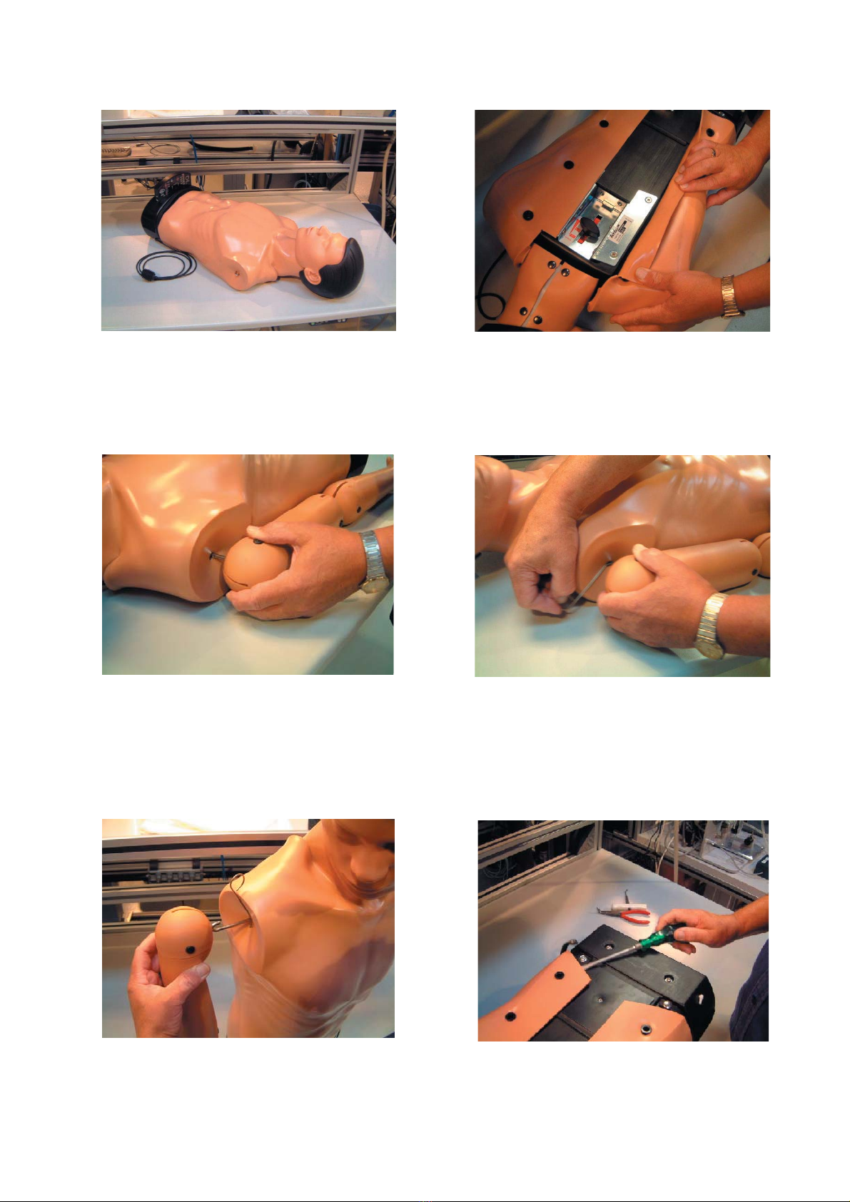
3.1- 6 Undo the strap at the back, gently using a
schrewdriver.
3.1 Removal of head and chest skin with neck from base unit
3.1-1 Ambu Man model C with monitoring instrument
and socket for connection of computer/interface.
3.1-2 Serial number may be found under thorax adjust-
ment.
3.1-3 Remove arms if fitted.
Pull the arms carefully away from the body. If necessary
hold onto the mounting using a pair of polygrip pliers.
3.1-5 Remove the hook from the arm hook.
3.1-4 Insert a hook of approx. 2 mm through the hole
in the arm hook. Detach the pin in the arm from the
hook in the shoulder.

Page 6
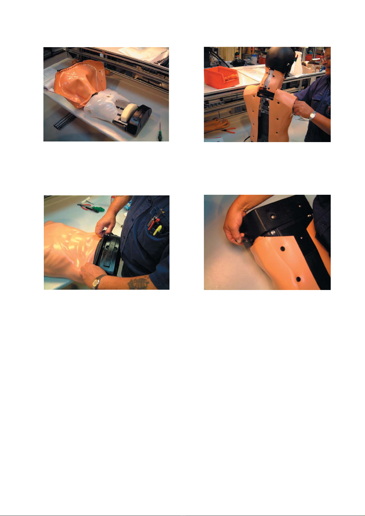
3.1-12 Remove by lifting each part of the chest.
During removal, treat as gently as possible.
3.1- 7 On new models from serie 55376, the neck is
attached with 4 buttons. This means that the skin can be
detached easily. The following disassembly instructions
and pictures will only show the “old” skin detachment.
3.1- 8 Undo the chest skin and the two parts of the
chest on the back of the Ambu Man.
3.1- 9 Free the chest skin from the base unit.
3.1-11 Pull the chest skin over the head and carefully
pull the chest skin free of the two hooks.
3.1-10 Lift the skin gently off the torso.

Page 7
3.1-18 Turn back the chest skin and carefully pull the
head and chest skin away from the base unit.
3.1-13 To free the part of the chest turn it completely.
3.1-15 Disengage the locking device
3.1-17 Disconnect the thin tube from the rocker level
and the other pulse tube from the base unit. Detach the
chest skin and neck piece from the base unit.
3.1-14 Remove the necktube from the connector.
3.1-16 Disengage the head by lifting the head mount-
ing free of the neck clamp pin.

Page 8
3.1-19 Loosen the skin on the neck mounting from the
notch on the outside of the neck piece.
3.1-21 To detach the head from the neck, insert a flat
piece of metal between the head mounting pin and the
side of the notch inside the neck (A).
3.1-20 Remove the head from the chest skin.
A

Page 9
3.2-6 Refit the two parts of the chest on the rocker
lever.
3.2 Assembly of head and chest skin with neck to base unit
3.2-1 Fit the chest skin onto the base unit. Replace the
head by inserting the head mounting
3.2-3 Fit the mounting with two hooks onto the neck
clamp pin.
3.2-5 Moisten the end of both parts with alcohol and
mount the neck tube to the tube connector.
3.2-2 Connect the two thin tubes - the short tube to
the connector on the rocker lever assembly and the long
tube to the extension tube on the base unit.
3.2-4 Mount the locking device.
Page 10
3.2-7 When repositioning the part of the chest, handle
the mounting with care in order not to stress the materi-
als.The retaining clamp for the two parts of the chest
must be replaced if damaged. Drill out the two pop
rivets, fit a new clamp, and re-rivet (see 6.1-16 and 17).
3.2-8 Fasten the parts of the chest and chest skin on
the back. For models with arms carefully pull the hooks
through the holes in the chest skin using a pair of
pointed pliers. (Photo shows new “neck” model)
3.2-9 Attach the chest skin to the groove in the base
unit.
3.2-10 Lock the plastic straps on the backside, locking
the skin to the base. Observe the groove at the skin.
Otros manuales para Man
1
Tabla de contenidos
Otros manuales de Mobiliario de interior de Ambu


