ALW SuperPlane 4 Manual de usuario

A1035 22nd Avenue, Unit 1 nOakland, CA 94606 P510.489.2530 ETalkToUs@alwusa.com Walwusa.com
INSTALLATION INSTRUCTIONS
SUPERPLANE 4
Trim
SP4R Trim Installation Guide 2 of 12 102-000022 - IG011619-A.0
SP4R - Safety & Warnings!
1. Read all instructions.
2. Install in accordance with national and local electrical code regulations.
3. This product is intended to be installed and serviced by a qualied, licensed electrician.
4. Do not install in wet locations. For dry and damp use only.
5. Turn off electrical power before installing or servicing xture in any way.
6. To reduce the risk of re and overheating, make sure all connections are tight.
7. This product is type IC (insulation contact) rated, and suitable for continuous row mounting.
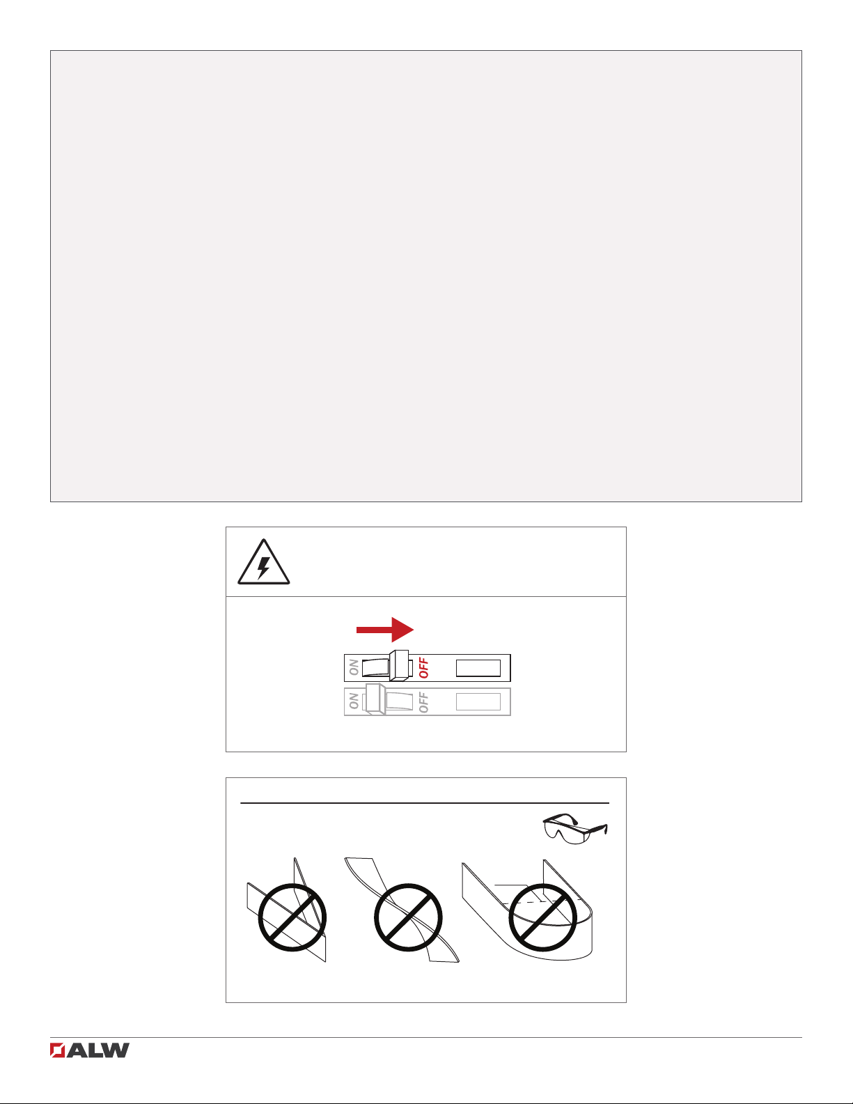
8. Handle ControRollTM lens with care! Always wear protective eyewear while handling lens! Lens may
chip/crack when handled roughly.
1. Lisez toutes les instructions.
2. Installez conformément à la réglementation du code électrique national et local.
3. Ce produit est destiné à être installé et entretenu par un électricien agréé qualié.
4. Ne pas installer à l’extérieur ou dans des endroits humides. Pour une utilisation en intérieur et sec
seulement.
5. Coupez l’alimentation électrique avant de évoluer le système d’éclairage en aucune façon.
6. Pour réduire le risque d’incendie et de surchauffe, assurez-vous que toutes les connexions sont bien
serrées.
7. Type IC. Pour emplacements secs seulement . Peut être monté en rangée continue.
8. Manipuler l’objectif ControlRoll avec soin! Portez toujours des lunettes de protection lors de la manip-
ulation de l’objectif ControlRoll.
SP4R - Attention!
Ø < 3.0 in.
CONTROLROLL™ LENS HANDLING & SAFETY!
DO NOT CREASE LENS DO NOT TWIST LENS DO NOT BEND LENS TO A
DIAMETER LESS THAN 3 INCHES.
ALWAYS WEAR PROTECTIVE EYEWEAR WHILE HANDLING LENS!
LENS MAY CHIP/CRACK WHEN HANDLED ROUGHLY!
SHOCK HAZARD! May result in serious injury or
death. Turn power OFF at circuit breaker prior
to installation or servicing.

SP4R Trim Installation Guide SP4R Trim Installation Guide 3 of 12 102-000022 - IG011619-A.0
Table of Contents
Luminaire Overview
Included Parts
Parts (by others)
Tools Required
Installation
Mounting to Structure
Joining Straight Sections
ControllRollTM Lens
Wiring Diagrams
Troubleshooting
Diagram
Traditional On/Off
0-10V Dimming
DMX
DALI
Lutron LDE
4
4
4
4
4
5
5
7
10
11
11
11
11
11
11
12
Joining Mitered Corners 8
Inside Corners 9
Outside Corners 9
Quick Specs 4
Installing Emitter 6

SP4R Trim Installation Guide SP4R Trim Installation Guide 4 of 12 102-000022 - IG011619-A.0
Included Parts
flush: 43⁄4"
regress: 51⁄2"
53⁄4"
f
lush
:
3
5
⁄
5
8
⁄
⁄
"
re
g
ress
:
4
3
⁄
3
8
⁄⁄
"
5
1
⁄
1
4
⁄
⁄
"
O
pening in drywall
Luminaire Overview
Cable conduit and conduit
ttings
Parts (by others)
Drill
#2 phillips bit
Drywall cutting tool
Tools Required
Wrench
Wire strippers
SP4R Fixture ControlRollTM Lens
1/8” Allen key
Diffuser Shim (miters) Joiner kit (lengths > 8ft)
Input Voltage / Frequency:
See product label
Rated Current:
See engineering drawing
Ambient Temperature:
-4° – 120°F (-20° – 50°C)
Environment:
Dry and damp locations
Quick Specs
Diagram
1/4-20 ceiling rods

SP4R Trim Installation Guide 5 of 12 102-000022 - IG011619-A.0SP4R Trim Installation Guide
Remove end cap window cover and punch knock-out.
Make connections per wiring diagram on page 11 and
secure conduit to window cover. Re-fasten cover ensur-
ing not to pinch wires between parts.
2Connect wiring
flush: 35⁄8"
regress: 43⁄8"
51⁄4"
Install 1⁄4”-20 threaded support rod 3 5⁄8inches above
ceiling plane for a ush lens and 4 3⁄8inches above ceiling
plane for regress. Install drywall with 5 1⁄4inch gap. See
submittal drawings for cutout length and exact rod posi-
tioning.
Note: Finish drywall and paint prior to mounting.
Raise xture into cutout and ensure correct opening
dimensions along xture length.
Tighten 1⁄4”-20 nut on support rod. Trim should now sit tight-
ly against nished drywall.
1Install support rod and drywall 3Raise xture into ceiling
4Mount xture to support rods
Installation: Mounting to Structure
SHOCK HAZARD! May result in serious injury or
death. Turn power OFF at circuit breaker prior to
installation or servicing.
!
DO NOT PINCH OR PUT EXCESSIVE TENSION ON
WIRES while joining sections or reattaching end
caps.
Note: End cap not
shown for clarity.
Note: End cap not
shown for clarity.

SP4R Trim Installation Guide SP4R Trim Installation Guide 6 of 12 102-000022 - IG011619-A.0
If joining straight sections,
continue with steps 8-10.
If joining miter sections,
continue with steps 11-14.
If installing single-section
xtures, go to step 15.
Re-install emitter by snapping emitter arms to main extru-
sion. Do not pinch wires.
6Install end emitter
Connect wiring quick connects between xture and
emitter assembly.
5Connect emitter wiring
Installation: Installing Emitter
7ASecure end emitter
7BSecure end emitter
Secure end emitter assembly to xture using #6 screws
(4X).

SP4R Trim Installation Guide SP4R Trim Installation Guide 7 of 12 102-000022 - IG011619-A.0
8Connect wiring
Connect wiring quick-connects and move joining xture
section into place.
9Mount to structure
10 Connect internal brackets
Connect internal brackets with included screws. Make
sure there is no gap between xture segments. See steps
5 - 7 to install emitter at joint.
Mount joining xture to structure as shown in steps 3 - 4.
Installation: Joining Straight Sections
SHOCK HAZARD! May result in serious injury or
death. Turn power OFF at circuit breaker prior to
installation or servicing.
!
DO NOT PINCH OR PUT EXCESSIVE TENSION ON
WIRES while joining sections or reattaching end
caps.

SP4R Trim Installation Guide SP4R Trim Installation Guide 8 of 12 102-000022 - IG011619-A.0
SHOCK HAZARD! May result in serious injury or
death. Turn power OFF at circuit breaker prior to
installation or servicing.
!
DO NOT PINCH OR PUT EXCESSIVE TENSION ON
WIRES while joining sections or reattaching end
caps.
Installation: Joining Mitered Corners
12 Join miter sections
13 Connect brackets
Slide miter sections together and join section connectors.
Adjust connectors with set screws as necessary.
Screw connector brackets on top and sides with provid-
ed 8-32 screws avoiding any gaps between xtures. See
steps 5 - 7 to install emitter at joint.
11 Connect wiring
Connect wiring quick connects between xtrue sections.
14AInsert diffuser shim
Bend provided diffuser shim and insert it into the grooves
in side walls of extrusion covering LEDs extending into
miter joint.
14BInsert diffuser shim

SP4R Trim Installation Guide 9 of 12 102-000022 - IG011619-A.0
Inside corner
Inside corner
Outside corner
Outside corner
Install xture sections, make connections, and install
lenses.
Installation: Inside Corner
Inside corner
Install xture sections, make connections, and install
lenses.
Installation: Outside Corner
Outside corner

SP4R Trim Installation Guide SP4R Trim Installation Guide 10 of 12 102-000022 - IG011619-A.0
15 Bring lens to xture
16AInsert ControlRoll lens into lens channel
16BInsert ControlRoll lens into lens channel
Raise ControlRollTM lens to xture. For longer xture lengths,
two people may be needed. Always wear protective
eyewear while handling lens.
Insert one edge ControlRoll lens into lens channel.
17APress lens into lens channel
17BPress lens into lens channel
18 Snap lens along xture
With rst edge of lens in lens channel, press other side
of lens up toward opposite channel. It may be easier to
begin installing lens 2 or more inches from end of xture.
Once inserted, lens can be slid to meet end cap.
Push lens upward until it snaps into second lens channel.
Continue pressing both sides of lens into lens channel until
lens is fully installed along length of xture. Press lens into
channel at offset positions as shown to limit stress on lens.
Installation: ControlRollTM Lens
Tabla de contenidos
Otros manuales de Luminaria de ALW


Manuales populares de Luminaria de otras marcas

Emos
Emos CLASSIC ZY1431T Manual de usuario

Westinghouse
Westinghouse Outdoor Lighting Fixture Manual de usuario

Hedler
Hedler C 12 silent Manual de usuario

Blizzard Lighting
Blizzard Lighting Puck: CSI Manual de usuario

Energetic Lighting
Energetic Lighting ELYSL-5004 Series Manual de usuario

Lightmaxx
Lightmaxx Shaft 5R Manual de usuario


Cooper Lighting
Cooper Lighting Halo L3232E Manual de usuario

Stageline
Stageline ODW-2410RGBW Manual de usuario

Light Sky
Light Sky Tornado Series Manual de usuario

Lightolier
Lightolier Paralyte 2424 PLA2G9LS26U Manual de usuario

Lightolier
Lightolier Lytespan 83ED17S Manual de usuario

Lightolier
Lightolier Calculite CS8226 Manual de usuario