AlsoEnergy PowerLogger 1000 Manual de usuario

AlsoEnergy PowerLogger
Contents
1. Installation Overview........................................................................ Error! Bookmark not defined.
1.1 Setting up PowerLogger ...........................................................................................................3
- Connect 24 VDC power to the top of PowerLogger .......................................................................3

- Connect Ethernet cable from local LAN network ...........................................................................3
- Connect the MODBUS R485 devices to the PowerLogger in port 1 or 2........................................ 3
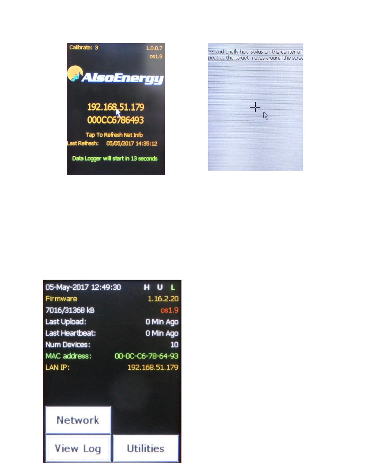
1.2 Loading screen ..........................................................................................................................3
1.3 Data Logger main screen...........................................................................................................4
1.4 Network Configuration screen..................................................................................................6
1.4.1 Network Testing .........................................................................................................6
1.5 Utilities ......................................................................................................................................8
1.5.1 Bus Tools .................................................................................................................... 9
1.5.1.1 Bus Scan........................................................................................................ 9
1.5.1.2 Device Ping Test..........................................................................................10
1.5.1.3 Bus Test Raw...............................................................................................10
1.5.1.4 Register Watch ...........................................................................................11
2. Power Logger configuration in PT...…………………………………………………………………………………………..10
2.1 Creating the device in PT ………………………………………………………………………………………………….10
2.2 Device screen in PT …………………………………………………………………………………………………………..12
2.2.1 Tabs ……………………………………………………………………………………………………………………….12
2.2.1.1 Configuration.…………………………………………………………….….………………….…..12
2.2.1.2 Data.……………………………………………………………………………………………………...14
2.2.1.3 Events …………………………………………………………………………………………………...14
2.2.1.4 Alerts …………………………………………………………………………………………………….14
3. PowerLogger Standard Operation .................................................................................................36
4. Networking Ports .........................................................................................................................186
5. Specifications ...............................................................................................................................186
6. Troubleshooting...........................................................................................................................207

Installation Overview
1. Mount PowerLogger 1000
1.1. Connect 24 VDC power to the top of PowerLogger 1000.
1.2. Connect Ethernet cable from LAN network.
1.3. Connect the MODBUS RS485 devices to the PowerLogger 1000 in port 1 or 2.
PORT 1
PORT 2
GROUND
10
14
DATA +
11
15
DATA −
12
16
SHIELD
13
17
*TR is a 120Ωtermination resistor.
Jump TR to Data- if termination is required.
There will be two wires on the Data- terminal.
1.4 After all connections are complete turn power on.
2. Loading Screen
On power on the loading screen appears, the logger program will start in 30 seconds.

Local IP address and MAC address are shown.
Screen Calibration can be accessed with 3 taps on
the loading screen.
3. PowerLogger 1000 Home Screen
Information shown on this screen:
•Time/date
•H U L: Heartbeat, Upload, Logging
•Firmware version (1.16.2.20)
•OS version (OS1.9)
•Last Upload: Last time that data has been sent to
PowerTrack
•Last Heartbeat: Last time that the PowerLogger
heartbeat to PowerTrack
•Num Devices: Number of devices configured in
PowerTrack that are associated to the

PowerLogger. (PowerLogger counts as one
device.)
•MAC Address of the LAN port
•LAN IP: Local IP address
•At the bottom of the screen we can see three
active buttons: Network, View Log, Utilities.

4. Network Configuration Screen
This screen shows information like the IP address,
subnet, gateway, MAC address, and Static or DCHP.
If any changes in the network configuration need to
be made, we can use the “Set IP/Net” option to
change IP settings.
Network Testing
Use the “Quick test” button to test the internet connection

On the Quick Test screen, click Start to begin
test.
Once we start the test we will automatically see the
network status and AE communication status, as
well as other information regarding time or SD card
and NAND writing function.
This screen shows a successful test.

5. Utilities
•Bus Tools: Device specific testing to scan the
port, ping the device, watch registers and test the
bus.
•Get Config: After changing settings or adding a
device in PowerTrack, use Get Config to
immediately sync new configuration settings to
PowerLogger (to refresh the server cache is
required before this step).
•Read Inputs: It gives information about some
inputs state, as well as board temperature or
input voltage
•Start Threads: Start all processing
•Stop Threads: Stop all processing
•Backlight: Allows to change the backlight
intensity.
•Reboot: It will reboot the PowerLogger
•Beep Test: Test the buzzer in the PowerLogger
•Storage Format: Format the SD card
•Clear All Errors
•Port Test

6. Port Tools
These tools can be used to test devices on the
serial ports or the Ethernet network.
6.1. Port Scan
Bus Scan function will scan the bus to see what
devices are connected to the PowerLogger.
Select:
•Baud rate
•RS485 port to scan (P1/P2)
•Scan range (1-255).
The window on the right will show the device ID
followed by ERR or OK. If it says OK, that means
that there is a device with that ID connected to
that port.
This utility is useful to find unknown devices on the
port. Scanning all valid addresses (1-255) to see
how many devices are connected on the RS485
port and what their IDs are.

6.2. Device Ping Test
Ping test allow us to ping any device programed to
the PowerLogger in PowerTrack. The device
number that we can see on the screen matches
with the PowerTrack ID number of each device as
seen in the upper right of the Hardware section on
PowerTrack.
6.3. Bus Test Raw
Bus Test will allow testing of devices already
configured for the PowerLogger on the PowerTrack
monitoring. Select the device ID and click Start.
Tabla de contenidos
Otros manuales de Registrador de datos de AlsoEnergy


