AJAX vhfBridge Manual de usuario

vhfBridge User manual
Updated August 8, 2023
vhfBridge is a module for connecting Ajax security systems to third-party VHF
transmitters. It provides 8 transistor outputs for connection to third-party VHF
transmitters.
The device is powered from 100–240 V~ mains and can be operated from a 12
V
⎓
backup battery.
vhfBridge operates as part of the Ajax security system and connects to the hub
via the secure radio communication protocol. The hub communication
range is up to 1,800 meters without obstacles. Supplied in two congurations:
with a casing and without it.
Functional elements
Casing elements
Jeweller
Buy vhfBridge
We value your privacy
We use cookies to enhance your browsing experience, serve personalized ads or content, and analyze our trac. By
clicking "Accept All", you consent to our use of cookies.Cookie Policy
Reject All Accept AllCustomize

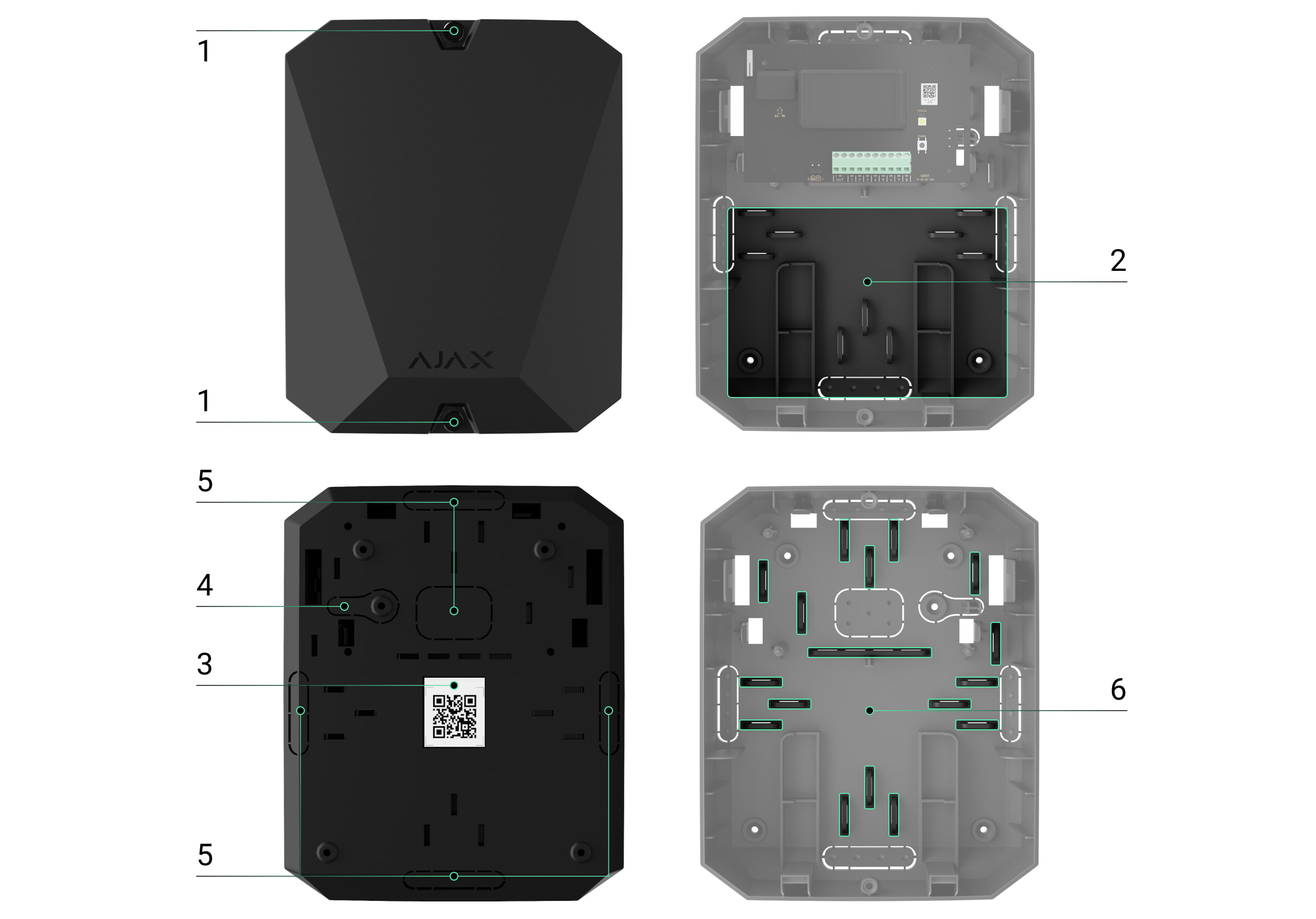
vhfBridge board elements
1. Screws securing the casing lid. Unscrew with a bundled hexagon key (Ø
4mm).
2. Space for a 12 V
⎓
backup battery.
Battery not included with vhfBridge set.
3. QR code with the device ID. It is used to pair the device with the Ajax
security system.
4. Perforated part of the casing. Necessary for tamper triggering in case of any
attempt to detach the device from the surface.
5. Perforated parts of the casing for cable output.
The presence of the casing depends on the vhfBridge package. The device is
supplied in two congurations: with a casing and without it.
We value your privacy
We use cookies to enhance your browsing experience, serve personalized ads or content, and analyze our trac. By
clicking "Accept All", you consent to our use of cookies.Cookie Policy

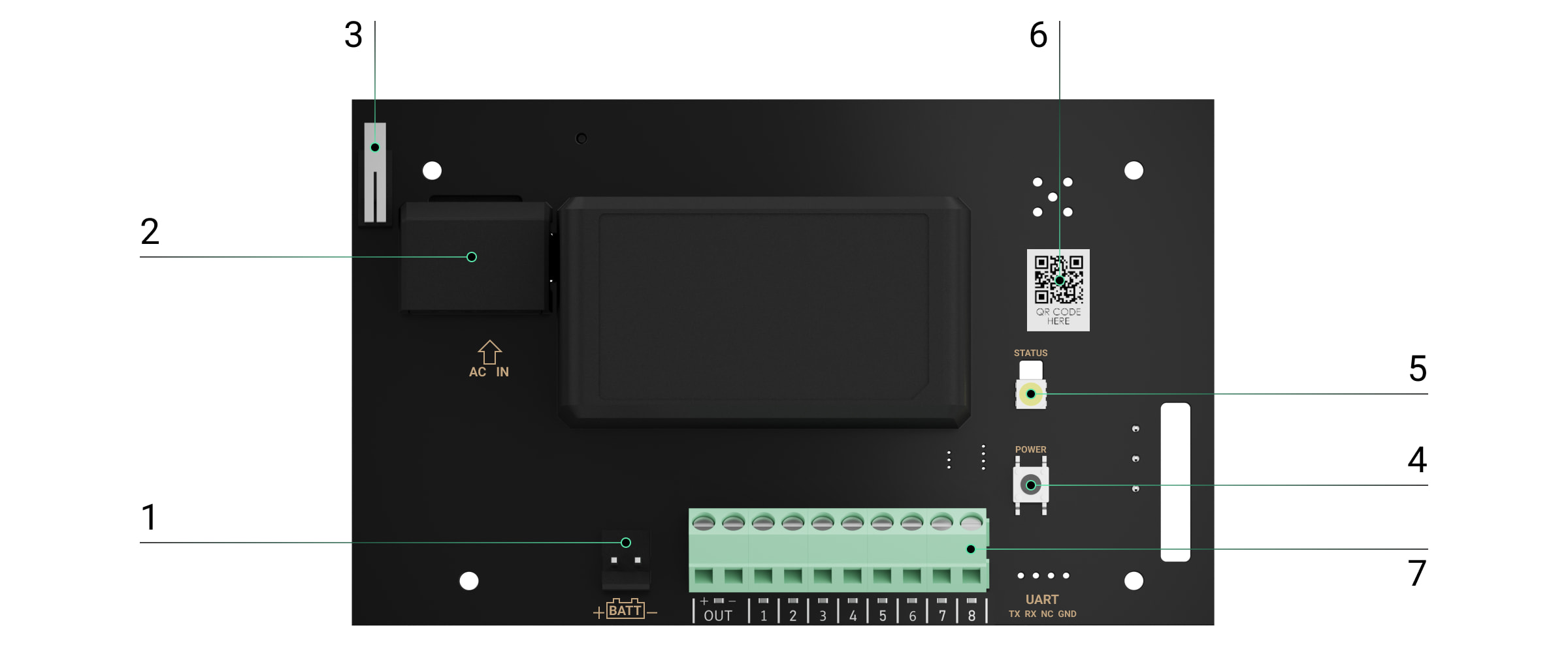
vhfBridge terminals
1. Terminals for connecting a 12 V
⎓
backup battery.
2. 100–240 V~ power supply input.
3. Tamper button. Signals if vhfBridge casing lid is removed.
4. Power button.
5. LED indicator.
6. QR code with the device ID. It is used to pair the device with the Ajax
security system.
7. Terminals for connecting a VHF transmitter.
BATT — input for the 12 V
⎓
backup power connection.
We value your privacy
We use cookies to enhance your browsing experience, serve personalized ads or content, and analyze our trac. By
clicking "Accept All", you consent to our use of cookies.Cookie Policy

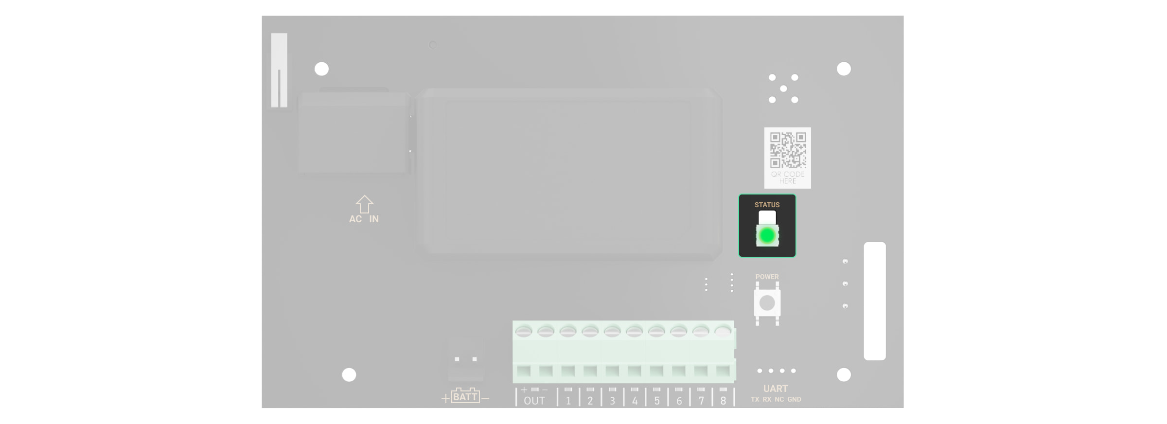
LED indication
vhfBridge LED indicator may light up white, red, or green, depending on the
status of the device.
Please note that the LED indicator is not visible when the casing lid is closed.
The LED indicator is used at the stage of vhfBridge connecting and conguring.
Later on, the state of the device can be monitored in the Ajax app.
LED indication Event Note
Lights up white.
Connection with the hub is
established, external power
supply is connected.
Lights up red.
There is no connection with
the hub, external power supply
is connected.
For example, the hub is turned
off or vhfBridgeis outside the
coverage area of the hub’s
wireless network.
Goes out for 0.5 seconds, then
lights up green and turns off. Enabling vhfBridge.
Goes out for 0.5 seconds, then
lights up green and fades out
over 3 seconds.
Disabling vhfBridge.
OUT — power output for the 12 V
⎓
VHF transmitter (maximum output
current is 2 A).
OUT 1…8— vhfBridge outputs for connecting a VHF transmitter.
We value your privacy
We use cookies to enhance your browsing experience, serve personalized ads or content, and analyze our trac. By
clicking "Accept All", you consent to our use of cookies.Cookie Policy

Blinks red once per second. vhfBridge is not assigned to a
hub.
Lights up for a second once
every 10seconds.
No external power supply is
connected to vhfBridge.
The colour of the indication
depends on the status of
connection with the hub:
During an alarm, gradually
lights up and goes out once
every 10seconds.
No external power supply and
discharged external battery of
vhfBridge.
The colour of the indication
depends on the status of
connection with the hub:
LED indication of output status
LED indication Output status in case of alarm
High potential output (positive trip). Lights up green.
Low potential output (negative trip). Goes out.
Operating principle
vhfBridge is designed to connect third-party VHF transmitters to create an
additional channel for transmitting events to the CMS.
The communication channel with the CMS created using vhfBridge can be used
as the only or as a backup channel for communicating with the CMS
(recommended more reliable option). This means that the hub can
simultaneously transmit all events and alarms to the monitoring station of the
lights up white if there is
connection with the hub;
lights up red if there is no
connection with the hub.
lights up white if there is
connection with the hub;
lights up red if there is no
connection with the hub.
We value your privacy
We use cookies to enhance your browsing experience, serve personalized ads or content, and analyze our trac. By
clicking "Accept All", you consent to our use of cookies.Cookie Policy

security company not only through SIA (DC-09), ADEMCO 685, SurGard (Contact
ID), and other proprietary protocols but also using vhfBridge.
The transponder receives information about alarms and events from the hub via
the Jeweller radio channel. Then, vhfBridge transmits it to a third-party VHF
transmitter via wires. The VHF transmitter, in turn, transmits all events and
alarms to the CMS via a radio channel.
Events can be transmitted to the CMS via the Internet and vhfBridge in parallel.
Transmission via the Internet works as the main channel because of greater
reliability and informativity. The transmitted events may contain the zone
number of the triggered detector, group number, user number, and other data.
vhfBridge works as a backup communication channel duplicating all events
transmitted via the Internet. The delivery speed of events and alarms in both
cases does not exceed 1second.
An example of the algorithm of actions in case of an alarm from a
MotionProtect motion detector:
1. MotionProtect has detected an alarm.
2. MotionProtect transmits the alarm to the hub via the Jeweller radio
protocol.
3. The hub receives the MotionProtect alarm and transmits it to vhfBridge via
the Jeweller radio protocol.
4. vhfBridge receives the alarm from the hub and transmits it to the VHF
transmitter over a wired connection.
00:00
00:12
We value your privacy
We use cookies to enhance your browsing experience, serve personalized ads or content, and analyze our trac. By
clicking "Accept All", you consent to our use of cookies.Cookie Policy

Output types
vhfBridge has 8 potential outputs for connection to a VHF transmitter. There are
two types of outputs:
The high-potential output does not supply voltage in the normal state. As soon as an
alarm or event occurs, the output supplies a voltage of 12–14 V
⎓
. The low-potential
output works the other way around. In the normal state, the voltage is maintained at 12–
14 V
⎓
, and when an alarm or event occurs, it drops to 0 V.
The vhfBridge output type and alarm pulse duration are congurable in Ajax
apps.
VHF transmitter power supply
vhfBridge can supply a third-party VHF transmitter with 12 V
⎓
power (maximum
output current is 2 A).
If the VHF transmitter has a current consumption of more than 2 A, it can be
powered by the vhfBridge battery. In this case, disable battery charge tracking in
the vhfBridge settings so that the system users do not receive notications
about the vhfBridge battery charging too long.
Sending events to the Central Monitoring Station (CMS)
The Ajax security system can transmit alarms to the monitoring
app as well as the Central Monitoring Station (CMS) using SurGard (Contact ID),
5. The VHF transmitter receives the alarm and transmits it to the radio receiver
on the CMS side via the radio channel.
6. The radio receiver receives the alarm and transmits it to the CMS software.
7. The CMS receives and processes the alarm.
1. High potential output (positive trip).
2. Low potential output (negative trip).
PRO Desktop
We value your privacy
We use cookies to enhance your browsing experience, serve personalized ads or content, and analyze our trac. By
clicking "Accept All", you consent to our use of cookies.Cookie Policy

SIA DC-09 (ADM-CID), ADEMCO 685, and other proprietary protocols. The list of
supported protocols is .
When an alarm is received, the monitoring station operator of the security
company knows what happened and where the rapid response unit has to be
sent. All Ajax devices are addressable, so events, the device type, its assigned
name and room can be transmitted to the PRO Desktop and the CMS. The list of
transmitted parameters may differ depending on the type of the CMS and the
selected communication protocol.
You can nd vhfBridge ID and zone number in the in Ajax apps. The device
number corresponds to the loop (zone) number.
Adding to the system
vhfBridge doesn’t work with Hub, ocBridge Plus, uartBridge and third-party security
central units. The device can only be added and congured through the Ajax PRO app by
a user with administrator rights.
Before adding a device
Only one vhfBridge module can be connected to one compatible Ajax hub.
available here
Which CMSs can the Ajax security system be connected to
States
1. Install the . Create Add a hub to the app and
create at least one virtual room.
Ajax PRO app an account.
2. Check that the hub is on and has access to the Internet:via Ethernet cable,
Wi-Fi, and/or mobile network. You can do this in the Ajax app or by checking
the hub logo on the faceplate. It should light up white or green if the hub is
connected to the network.
3. Check the status of the hub in the Ajax app and make sure that it is
disarmed and does not start updates.
We value your privacy
We use cookies to enhance your browsing experience, serve personalized ads or content, and analyze our trac. By
clicking "Accept All", you consent to our use of cookies.Cookie Policy

To connect vhfBridge
Please note that to nd and pair the device, the transponder should be located within the
hub’s radio communication range (on the same secured premises).
If the connection has failed, disconnect vhfBridge for 5seconds and try again. If
the transponder has already been assigned to another hub, turn off vhfBridge
and then follow the standard addition procedure.
The connected transponder will appear in the list of hub devices in the app.
Device status updates depend on settings. The default status update
period in the app is 36seconds.
Malfunction counter
1. Open the Ajax app. If your account has access to multiple hubs, select the
one to which you want to add vhfBridge.
2. Go to the Devices menu and click Add Device.
3. Name the transponder, scan or enter the QR code manually (located on the
device casing and packaging), and select a room and a group (if the group
mode is activated).
4. Click Add — the countdown will begin.
5. Switch on vhfBridge by holding the power button for 3seconds. Keep in
mind that the hub connection request is only sent when the integration
module is turning on.
Jeweller
We value your privacy
We use cookies to enhance your browsing experience, serve personalized ads or content, and analyze our trac. By
clicking "Accept All", you consent to our use of cookies.Cookie Policy

When a vhfBridge malfunction is detected (e.g., no external power), the Ajax app
will display a red icon with a number in the upper left corner of the device icon.
This number indicates the number of malfunctions.
All malfunctions can be seen in the transponder states. Fields with malfunctions
will be highlighted in red.
Icons
Icons display some of the vhfBridge states. You can check them in the Ajax app
in the Devices tab.
We value your privacy
We use cookies to enhance your browsing experience, serve personalized ads or content, and analyze our trac. By
clicking "Accept All", you consent to our use of cookies.Cookie Policy
Otros manuales para vhfBridge
2
Este manual sirve para los siguientes modelos
1
Tabla de contenidos
Otros manuales de Transmisor de AJAX

Manuales populares de Transmisor de otras marcas


Dejero
Dejero EnGo 3x Manual de usuario

Rosemount
Rosemount 4600 Manual de usuario

Speaka Professional
Speaka Professional 2342740 Manual de usuario

trubomat
trubomat GAB 1000 Manual de usuario

Teledyne Analytical Instruments
Teledyne Analytical Instruments LXT-380 Manual de usuario

Rondish
Rondish UT-11 Manual de usuario


