AerAtron FR3 Series Instrucciones de instalación y funcionamiento

FR3 & FQ3 CEILING FAN
FR3
FQ3
Available in: 43”/1070mm 50”/1270mm 60”/1524mm - FR3 model only
LED light kit and ceiling extension kit are oponal for all AeratronTM models
USER MANUAL & INSTALLATION GUIDE
ATTENTION ELECTRICIANS
An isolaon switch per fan is highly recommended
WARNING: If unusual oscilang movement is observed, immediately
stop using the ceiling fan and contact the naonal distributor/retailer

Important information - Please read before attempting installation
1
!
This fan must be installed by a licensed and qualified
electrician according to local authority regulaons.
*DIY installaon allowed in some countries*
1. Please read these instrucons carefully, be mindful of all warnings and safety informaon shown throughout
this manual. Should you have any quesons please call your local agent.
2. Please review the accompanying assembly diagrams before aempng installaon.
3. This fan MUST be installed by a licensed & qualified electrician according to local authority regulaons and in
accordance with current wiring rules of the country/state.
4. A copy of the purchasing receipt and proof of installaon by a licensed and qualified electrician according to
local authority regulaons is required for all warranty claims.
4a. DIY installaon requires proof of purchase only.
5. Where special access equipment is required to service the fan in accordance with local authority regulaons all
associated costs are the responsibility of the owner.
6. Should a warranty claim be required, we reserve the right to charge a service fee for all call outs where the
fan is found not to be defecve and / or where access is not provided.
7. To enable future programming, maintenance, cleaning and troubleshoong an isolaon switch per fan is highly
recommended. Without an isolaon switch per fan, an electrician maybe required to assist with programming,
maintenance, cleaning and troubleshoong. All associated costs are the responsibility of the owner.
8. A Maximum of 8 fans on each RCD / circuit is recommended. The fans are a Class 5 Device with leakage to
Earth.
9. Your warranty will be void if a solid state dimmer or any other brand of wall controller is used.
10. The means for mains power disconnecon must be incorporated in the fixed wiring in accordance with
naonal wiring rules.
11. To avoid possible electric shock during installaon, be sure electricity is turned off at the main power box
before commencing work. Disconnect power by removing fuse or turning off circuit breaker before installing
the fan. Ensure all spliced connecons are adequately insulated.
12. Warning! Do not allow the rotang fan blades to come into contact with any object, this can cause serious
injury or death.
13. Damage caused by incorrect installaon, Force-majeure, lightning, electrical surges & spikes, exposure to
water, pests or moisture is not covered under warranty.
14. This appliance is not intended for use by persons (including children) with reduced physical, sensory or mental
capabilies, or lack of experience and knowledge, unless they have been given supervision or instrucon
concerning use of the appliance by a person responsible for their safety.
15. Suspension System
· the replacement of parts of the safety suspension system device shall be performed by the manufacturer, its
service agent, or suitably qualified persons.
· fixing means for aachment to the ceiling such as hooks, or other devices shall be fixed with a sufficient
strength to withstand 4 mes the weight of the ceiling fan.
· the mounng of the suspension system shall be performed by the manufacturer, its service agent, or suitably
qualified persons
· the model or type reference of a luminaire that may be installed in a fan must be constructed for this purpose
Australia, New Zealand: In accordance with AS/NZS60355-1 & ASNZS60355-2-80: “This appliance is not
intended for use by persons (including children) with reduced physical, sensory or mental capabilies, or lack
of experience and knowledge, unless they have been given supervision or instrucon concerning use of the
appliance by a person responsible for their safety. Children should be supervised to ensure that they do not
play with the appliance.”

Contents
2
IMPORTANT
assistance before leaving the site.
Important Informaon ................................................................................................................ 1
Contents ...................................................................................................................................... 2
Unpacking your fan ..................................................................................................................... 3
Installing your Fan ....................................................................................................................... 4
STEP1 Mounng the Hanger Bracket to Ceiling....................................................................... 4
STEP 2 Connecng Mains Power to Terminal Block................................................................. 4
STEP 3 Inserng Fan Motor into Hanger Bracket..................................................................... 5
STEP 4 Installing Receiver into Hanger Bracket ....................................................................... 5
STEP 5 Connecng Receiver..................................................................................................... 6
STEP 6 Pairing the Remote Control ......................................................................................... 7
STEP 7 Aaching the Fan Motor Housing ................................................................................ 8
STEP 8 Assembling the Fan Blades........................................................................................ 8,9
STEP 9 Aaching the Fan Blades ............................................................................................. 9
Opon A - LED Light Kit ............................................................................................................. 10
Opon B - Ceiling Extension Kit................................................................................................. 10
Opon C - Raked Ceiling Kit....................................................................................................... 11
Technical Specificaon .............................................................................................................. 12
Care and Cleaning ..................................................................................................................... 13
Troubleshoong ........................................................................................................................ 13
If the fan is noisy .................................................................................................................... 13
If the fan rotates but does not create much airflow.............................................................. 13
General Informaon.................................................................................................................. 14
Normal Wear and Tear .......................................................................................................... 14
Ceiling Fan Warranty................................................................................................................. 14
Transfer of Warranty ............................................................................................................. 15
The following is NOT covered by warranty. ........................................................................... 15
Aeratron ceiling fan warranty details........................................................................................16

3
Unpacking your fan
Unpack your fan and examine all parts, you should have the following:
CEILING SPACER x 2
HANGER BRACKET
MOTOR ASSEMBLY
CONTROL RECEIVER
MOTOR HOUSING
50” FAN BLADE
X3
43”FAN BLADE
X3 OR 60”FAN BLADE
X3
OR
REMOTE CONTROL
HUB UPPER
HUB LOWER
AAA BATTERIES x2
OR
TIMBER SCREWS X 2
PIVOT LOCK X1
HUB SCREWS X 10
MACHINE SCREWS X 2
WASHER X 2 WASHER X 2
NOTE: Wall control / automaon control & wifi module components are not included;
please contact your local fan supplier for more informaon.
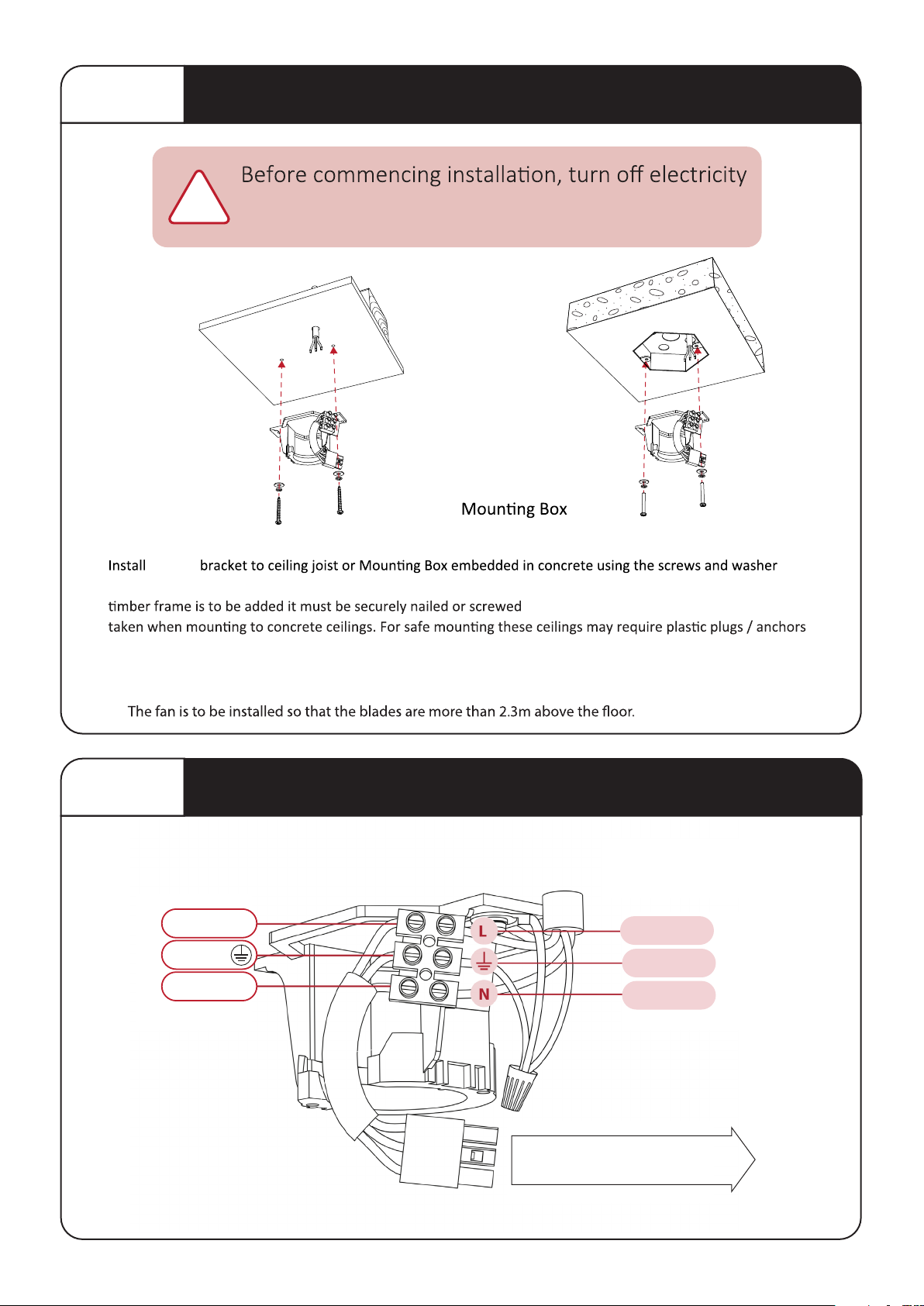
STEP 1 Mounting Hanger Bracket to Ceiling
supply at the main power box. Disconnect power
by removing fuse or turning off circuit breaker.
!
hanger
provided. Ensure ceiling joists are sound and of adequate size and strength to support a 32kg (70lbs) load. If a
between two beams.Proper care must be
and stronger screws.
Ceiling Joist
OPTION A: OPTION B:
Embedded
STEP 2 Connecting Mains Power to Terminal Block
4
WARNING: MOUNT ONLY TO AN OUTLET BOX MARKED ACCEPTABLE FOR FAN SUPPORT.
N
L
CONNECT WITH RECEIVER
3PIN
NEUTRAL
LIVE
L
LIVE
LIVE
GROUND
GREEN
BROWN L
BLUE N
FROM HOUSE
(Mains Power)

!
Inserting an otor into Hanger Bracket
=
Bracket Ensure that lug on Hanger
Ball
STEP 4
is engaged in slot in suspension
Installing Receiver into Hanger Bracket
5
STEP 3
Slide Remote Control Receiver
into Hanger Bracket from the
opposite side of the Terminal block
in the orientaon as shown below.
Oponal
Wifi module
Antenna

X0
6
Connecting the Receiver
STEP 5
Learn Switch
Switch to “O” to pair receiver
with the Remote control and
Switch to “X” to lock the pairing
code with the Remote control
2PIN LED driver connection
(optional for LED light)
3PIN
3PIN
Mains Power
Aerial
4PIN Comms
Connector
(Optional USE ONLY
IF INSTRUCTED)
1.
2.
Connect the 3PIN connector (Mains Power)
between Hanger Bracket and Reciever.
Connect the3PIN
& Earth cable connector
between DC Motor and Receiver.
3PIN
Receiver to
Hanger bracket
3PIN
Receiver
to Motor
Earth Cable

The remote control is pre-programmed
No pairing with the receiver required
STEP 6
!
Pairing the Remote Control
NOTE: Blades must be aached prior to tesng the fan
1. On Receiver: Verify that the “Learn” switch is in the “O” posion
2. Slide baery cover to unlock - Locate the LEARN BUTTON &
insert baeries.
3. Switch on the main power to acvate the receiver, indicated
by one beep. (Energise one fan reciever at a ame).
4. Within 60 seconds aer the power is turned on (one beep),
press and hold the LEARN buon on the Remote Control
(min. 3 secs.) unl Fan Receiver issues three ‘beeps’ which
indicates successful pairing.
5. On Receiver: switch the “Learn” switch to “X” (this will
lock the pairing code with the remote)
6. Finish STEP 7, 8 & 9 and press ON/SPEED buon to test
fan funcons.
7. To re-pair, repeat steps 3 to 5
NOTE: Power must be off for 10 seconds min. before repairing.
Pairing a Single Fan per remote control: LEARN MODE
The Remote Control and Fan Receiver will memorise the pairing
code for future use even if mains power is switched off.
LIGHT SWITCH: Select ON/OFF or DIMMING for the light funcon.
(Light will maintain last seng if turned off)
Controlling the Fan
1. Fan OFF
2. Fan ON & Speed 1-6
3. Forward / Reverse
Use Forward mode (counterclockwise) for cooling
Use Reverse mode (clockwise) to circulate warm air
4. Timer 2, 4 & 8hrs
5. Light ON/OFF
To DIM, press and HOLD light buon
to cycle from bright to dark.
(LIGHT SWITCH at DIMMING posion)
6. Breeze/Cycle through speeds randomly
One remote control can control up to 8 fans (within a 7m (23”) radius).On ALL receivers verify
that the “Learn” switch is in the “O” posion. Switch on the mains power to acvate ALL
receivers at the same me, indicated by one ‘beep’. Within 60 seconds, press and hold the
LEARN buon on the remote control (min. 3 seconds) unl fan receiver issues three ‘beeps’.
Pairing mulple fans per remote control.
2
4
5
4 6
4
3
1
O LIGHT DIMMING
‘LEARN’ BUTTONLIGHT SWITCH
| LIGHT ON/OFF
7

8
STEP 7 Attaching the Fan Motor Housing
Align the 3 tabs with the 3 holes on the
Housing and move upwards. Push tabs
inwards slightly before sliding upwards
STEP 8 Assembling the Fan Blades
A B
Place the Hub Upper onto a clean working area.
with the 2 holes in the Hub Upper.
screws for each Blade.
be used.
CLICK!
!
avoid damaging the fan/surface

C
Lock Screw
9
Attaching the Fan Blades
44
STEP Assembling the Fan Blades cont.
C D
Fasten the the Hub Lower from the top side
using the 3 Hub Screws.
Lower) into the recess. With care, turn the fan
over.
No liability is accepted if the Silicone ring is
removed or the Pivot Lock is installed
!
the clearance ‘X’ between
the ceiling and motor
housing is equal all way
round.
Align
Connector and slide fan
blades onto Drive Sha.
D
Hold/push up Fan Blades
and insert Pivot Lock,
sideways. Push Pivot Lock
Tighten Lock Screw
securely using screw driver.
Do not use power tools.
x
A
Pivot Connector
Silicone Ring
B
Pivot Lock
Silicone Ring
Light Hub Lower
(OPTIONAL)
STEP 9
8
Otros manuales para FR3 Series
1
Este manual sirve para los siguientes modelos
8
Tabla de contenidos
Otros manuales de Admirador de AerAtron

AerAtron
AerAtron AE2 Manual de usuario

AerAtron
AerAtron E502 Manual de usuario

AerAtron
AerAtron Ceiling Extension Manual de usuario

AerAtron
AerAtron AE2+ Series Instrucciones de instalación y funcionamiento

AerAtron
AerAtron FR3 Series Instrucciones de instalación y funcionamiento

AerAtron
AerAtron AE+2 Series Manual de usuario


