Industrial Electronic Devices
ADFweb.com Srl – IT31010 – Mareno – Treviso
PROFIBUS Slave / Modbus Master
Document code: MN67561_ENG Revision 1.2 Page 2 of 33
INDEX:
Page
INDEX 2
UPDATED DOCUMENTATION 2
REVISION LIST 2
WARNING 2
TRADEMARKS 2
SECURITY ALERT 3
EXAMPLE OF CONNECTION 4
CONNECTION SCHEME 5
CHARACTERISTICS 6
CONFIGURTION 6
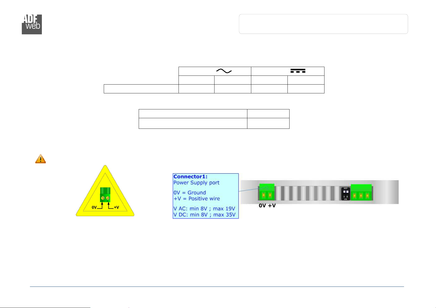
POWER SUPPLY 7
FUNCTION MODES 8
LEDS 9
PROFIBUS 1
RS485 1
RS232 11
USE OF COMPOSITOR SW67561 12
NEW CONFIGURATION / OPEN CONFIGURATION 13
SOFTWARE OPTIONS 14
SET COMMUNICATION 16
SET ACCESS 2
ERROR/DIAGNOSIS 24
GSD FILE 24
ASYNC MODBUS REQUEST 25
UPDATE VIA SERIAL 27
UPDATE VIA UDP 28
MECHANICAL DIMENSIONS 3
ORDERING INFORMATIONS 31
ACCESSORIES 31
DISCLAIMER 32
OTHER REGULATIONS AND STANDARDS 32
WARRANTIES AND TECHNICAL SUPPORT 33
RETURN POLICY 33
UPDATED DOCUMENTATION:
Dear customer, we thank you for your attention and we remind you that
you need to check that the following document is:
Updated
Related to the product you own
To obtain the most recently updated document, note the “document code”
that appears at the top right-hand corner of each page of this document.
With this “Document Code” go to web page www.adfweb.com/download/
and search for the corresponding code on the page. Click on the proper
“Document Code” and download the updates.
To obtain the updated documentation for the product that you own, note
the “Document Code” (Abbreviated written "Doc. Code" on the label on
the product) and download the updated from our web site
www.adfweb.com/download/
REVISION LIST:
Revision
Date Author
Chapter
Description
1. 4 3/11/2 1
Dp All Add new features
1. 5 15/ 1/2 13
Fl All Added new chapters
1.1 26/ 9/2 13
Dp All Added new Chapters
1.2 8/ 3/2 19
Fl All Revision
WARNING:
ADFweb.com reserves the right to change information in this manual
about our product without warning.
ADFweb.com is not responsible for any error this manual may contain.
TRADEMARKS:
All trademarks mentioned in this document belong to their respective
owners.