ACS contsys MIR-491 Manual de usuario

MIR-491
MIR-49
1
Industrial and process controller MIR-491
Operating manual
English
BAL-491-65511
Valid from: 07/2002
ACS-Control System GmbH

© ACS-Control System GmbH •Printed in Germany (0207)
All rights reserved. No part of this document may be reproduced or published in any form or by any means
without prior written permission from the copyright owner.
A publication of ACS-Control System GmbH
Lauterbachstraße 57 1/2
D-84307 Eggenfelden
Germany
BlueControl
More efficiency in engineering,
more overview in operating:
The projecting environment for the controller MIR-491
ATTENTION!
Mini Version and Updates on
www.acs-controlsystem.d
e
Description of symbols:
gGeneral information
aGeneral warning
lAttention: ESD sensitive devices

Contents
1Mounting ..............................5
2Electrical connections .......................6
2.1 Connecting diagram .........................6
2.2 Terminal connection.........................7
3Operation .............................10
3.1 Front view .............................10
3.2 Behaviour after power-on .....................11
3.3 Operating level ...........................11
3.4 Mainenance manager / Error list ..................12
3.5 Self-tuning .............................14
3.5.1 Selecting the method ( ConF/Cntr/tunE).............15
3.5.2 Self-tuning start .............................15
3.5.3 Optimization at the set-point ......................16
3.5.4 Self-tuning cancellation .........................17
3.5.5 Acknowledgement procedures in case of unsuccessful self-tuning. . . 17
3.5.6 Examples for self-tuning attempts ...................17
3.6 Manual self-tuning .........................19
3.7 Alarm handling...........................20
3.8 Operating structure.........................21
4Configuration level ........................22
4.1 Configuration survey........................22
4.2 Configuration parameters .....................23
4.3 Set-point processing ........................39
4.4 MIR-491 cooling functions ....................40
4.4.1 Standard ( CyCl=0) .........................40
4.4.2 Water cooling linear ( CyCl=1)...................40
4.4.3 Water cooling non-linear ( CyCl=2).................41
4.4.4 Heating and cooling with constant period ( CyCl=3)........42

4.5 Configuration examples ......................43
4.5.1 Signaller (inverse) ............................43
4.5.2 2-point controller (inverse) .......................44
4.5.3 3-point controller (relay & relay) ....................45
4.5.4 3-point stepping controller (relay & relay) ...............46
4.5.5 Continuous controller (inverse) .....................47
4.5.6 ∆-Y - Off controller ..........................48
4.5.7 MIR-491 with measured value output..................49
5Parameter setting level ......................50
5.1 Parameter survey ..........................50
5.2 Parameters .............................51
5.3 Input scaling ............................53
5.3.1 Input Inp.1 and InP.3 ........................54
5.3.2 Input InP.2...............................54
5.4 Second set of parameters......................54
6Calibration level .........................55
7Special functions .........................58
7.1 DAC®– motor actuator monitoring ...............58
7.2 MIR-491 as Modbus master ....................60
8BlueControl ............................61
9Versions ..............................62
10 Technical data...........................63
11 Safety hints ............................68
11.1 Resetting to factory setting.....................69
12 Notes ................................70
13 Index ................................74
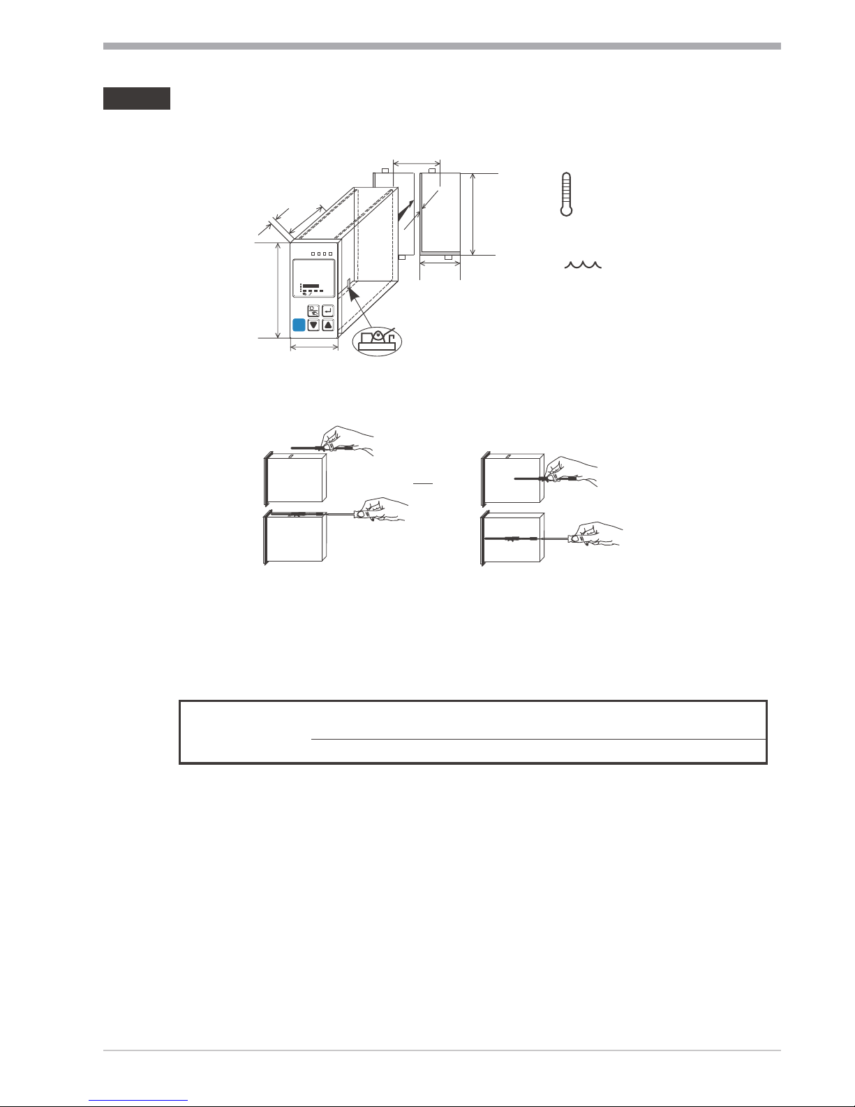
1Mounting
Safety switch:
For access to the safety switch, the controller must be withdrawn from the
housing. Squeeze the top and bottom of the front bezel between thumb and
forefinger and pull the controller firmly from the housing.
1Factory setting 2Default setting: display of all levels
suppressed, password PASS =OFF
lCaution! The unit contains ESD-sensitive components.
Mounting
Operating manual MIR-491 5
or:
%
max.
95% rel.
max. 60°C
0°Cmin.
96 (3.78")
48 (1.89")
Loc
min.48 (1.89")
10 (0.4")
1..10
(0.04..0.4")
118 (4.65")
45
+0,6
(1.77" )
+0.02
92
+0, 8
(3.62" )
+0. 03
*
Ü
*
Ü
Safety switch
MIR-491
123
è
1200
1199
°C
°F
SP.2
SP.E
para
func
Ada
Err
4
Loc open Access to the levels is as adjusted by means of
BlueControl (engineering tool) 2
closed 1all levels accessible wihout restriction

2Electrical connections
2.1 Connecting diagram
gThe controller is fitted with flat-pin terminals 1 x 6,3mm or 2 x 2,8mm
to DIN 46 244
Electrical connections
Connecting diagram 6 Operating manual MIR-491
1
3
4
5
6
7
8
9
10
11
12
13
14
15
17
(2)
(16)
mA
(mV)
(mV)
Volt
mA
INP2
INP3
INP1
di2
di1
1
2
3
4
5
6
7
8
9
10
11
12
13
14
15
Option
1
2
3
4
5
6
7
8
9
10
11
12
13
14
15
17
(16)
OUT1
OUT2
OUT3
OUT4
90...250V
24VUC
0%
100%
V
V
mA
HC
KS90-1. -2
5
...
KS90-1. -4...
KS90-1. -5...
KS90-1..-.1...
di2
di3
UT
RXD-B
GND
RXD-A
TXD-B
TXD-A
RS485 RS422
Modbus RTU
RGND
DATA B
DATA A
9
0
8
3
2
17
6
5
4
abcd
e
a
b
a
bc
d
e
+24V DC
24V GND
OUT5
OUT6
!

2.2 Terminal connection
Power supply connection 1
See chapter 10 "Technical data"
Connection of outputs OUT1/2 2
Relay outputs (250V/2A), potential-free
changeover contact
Connection of outputs OUT3/4 3
arelay (250V/2A), potential-free
changeover contact
universal output
bcurrent (0/4...20mA)
cvoltage (0/2...10V)
dtransmitter supply
elogic (0..20mA / 0..12V)
Connection of input INP1 4
Input for variable x1 (process value)
athermocouple
bresistance thermometer (Pt100/ Pt1000/ KTY/ ...)
ccurrent (0/4...20mA)
dvoltage (0/2...10V)
Connection of input INP2 5
aHeating current input (0...50mA AC)
or input for ext. set-point
(0/4...20mA)
bPotentiometer input for position
feedback
Connection of input INP3 6
As input INP1, but without voltage
Connection of inputs di1, di2 7
Digital input, configurable as switch or
push-button
Connection of inputs di2/3 8(option)
Digital inputs (24VDC external),
galvanically isolated, configurable as switch or push-button
Electrical connections
Operating manual MIR-491 7 Terminal connection
L
N
+
_
SSR
3
4
5
6
9
10
11
12
13
14
15
1
2
3
4
5
8
9
10
11
12
13
14
15
17
(16)
2
1
8
7
6
7
Logik
5INP2 current tansformer
6
9
10
11
12
13
14
15
1
2
3
4
5
6
7
8
9
10
11
12
13
14
17
(16)
L
N
+
5
43
2
1
8
7
15
2OUT1/2 heating/cooling

Connection of output UT9(option)
Supply voltage connection for external energization
Connection of outputs OUT5/6 0(option)
Digital outputs (opto-coupler), galvanic isolated, common positive control
voltage, output rating: 18...32VDC
Connection of bus interface !(option)
RS422/485 interface with Modbus RTU protocol
aIf the universal output OUT3 or
OUT4 is used there may be no
external galvanic connection
between measuring and output
circuits!
* Interface description Modbus RTU in speperate manual: see page 62.
Electrical connections
Terminal connection 8 Operating manual MIR-491
1
2
3
K
+
-
+
-
13V
22mA
13
14
15
11
12 13
17
(16)
14
15
12
11
10
3OUT3 transmitter supply
13
14
15
Option
17
(16)
1
3
4
5
6
7
8
9
10
11
12
13
14
15
17
(2)
(16)
+24VDC
5mA
5mA
0V
1
2
3
K
+
-
+
-
17,5V
22mA
14
13
+
-
15
OUT3
10
11
12
x
J
J
89 di2/3, 2-wire transmitter supply
1
3
4
5
6
7
8
9
10
11
12
13
14
15
17
(2)
(16)
option
1
3
4
5
6
7
8
9
10
11
12
13
14
15
17
(2)
(16)
option
1
3
4
5
6
7
8
9
10
11
12
13
14
15
17
(2)
(16)
option
11
12
13
14
15
10
11
12
13
14
15
10
11
12
13
14
15
RGND RGND RGND
RT
RS485-RS232
converter
PC
DATA A
DATA B
DATA A
DATA B
DATA A
DATA B
J
max. 1000m
"Twisted Pair” cable
10
RT
R=100 Ohm
RGND connection optional
R = 120...200 OhmT
R = 120...200 OhmT
9RS485 interface (with RS232-RS485 interface converter) *

MIR-491 connecting example:
aCAUTION: Using a temperature limiter is recommendable in
systems where overtemperature implies a fire hazard or
other risks.
Electrical connections
Operating manual MIR-491 9 Terminal connection
12
+
_
SSR
+
_
SSR
+
_
SSR
Series connection
Parallel connection
+
_
SSR
+
_
SSR
4V
4V
4V 12V
I =22mA
max
I =22mA
max
12V 11
10
10
11
12
Logic
3OUT3 as logic output with solid-state relay (series and parallel connection)
+
_
L
1
L2
N1
N2
Fuse
1
2
3
4
7
5
8
6
9
10
11
12
13
14
15
Fuse
TB 40-1
Temperature limiter
1
Fuse
SSR
Reset
key
Contactor
Heating
1TB 40-1 Temperature limiter
Standard version (3 relays):
TB40-100-0000D-000
Product of the PMA Prozeß- und
Maschinen-Automation GmbH
r
++
3
4
5
6
7
8
9
11
13
14
15
1
2
3
4
5
6
7
8
9
10
11
12
13
14
17
(16)
15
2
1
12
10
Logik
MIR-491

3Operation
3.1 Front view
LED colours:
LED 1, 2, 3, 4: yellow
Bargraph: red
other LEDs: red
gIn the upper display line, the process value is always displayed. At parameter,
configuration, calibration as well as extended operating level, the bottom display
line changes cyclically between parameter name and parameter value.
Operation
Front view 10 Operating manual MIR-491
MIR-491
123
(
1
2
3
4
5
6
$
7
8
%
&
(
è
è
è
/
1200
1199
°C
°F
SP.2
SP.E
para
func
Ada
Err
4
6
7
7
8
3
4
5
9
0
SP.2
E
§" !
rr
§"
"
1Status of switching outputs
OuT.1... 6
2Process value display
3Set-point, controller output
4Signals display on °C or °F
5Signals ConF and PArA level
6Signals aktive function key
7Self-tuning active
8Entry in error list
9Bargraph or clear text display
0SP.2 is effective
!SP.E is effective
"Set-point gradient effective
§Manual/automatic switch-over:
Off: Automatic
On: Manual
(changing possible)
Blinks: Manual
(changing not possible
(rConF/Cntr/MAn)
$Enter key:
calls up extended operating
level / error list
%Up/down keys:
changing the set-point or the
controller output value
&Manual mode /spec. function
(→ConF /LOGI )
/Freely programmable function
key
(PC connection for
BlueControl (engineering
tool)
Otros manuales para MIR-491
1
Tabla de contenidos
Otros manuales de Controladores de ACS contsys


