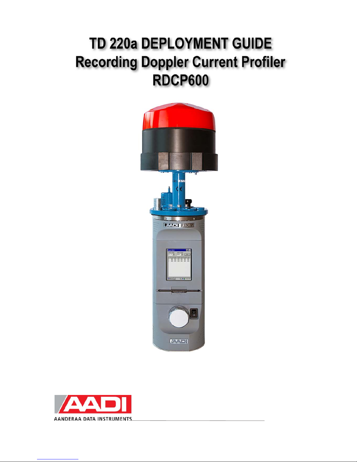
AADI RDCP600 Guía de referencia rápida
Reliable Solutions
AADI, a Xylem Analytics company

Page 2 JANUARY 2010 - TD 220a DEPLOYMENT GUIDE, RDCP600
1st Edition 10th July 2003 Preliminary edition
2nd Edition 6th November 2003
3rd Edition 27th September 2004
4th Edition 8th November 2004
5th Edition 31st January 2006 The old TD220 has been split in three parts: TD220a Deployment Guide,
TD220b RDCP Studio, TD220c RDCP Primer. Minor corrections.
6th Edition 31st October 2008
7th Edition 22nd January 2010 New mechanical design
© Copyright: Aanderaa Data Instruments AS
Contact information:
Aanderaa Data Instruments AS
PO BOX 34, Slåtthaug
5851 Bergen, NORWAY
Visiting address:
Nesttunbrekken 97
5221 Nesttun, Norway
TEL: +47 55 604800
FAX:+47 55 604801
E-MAIL: [email protected]
WEB: http://www.aadi.no

JANUARY 2010 - TD 220a DEPLOYMENT GUIDE, RDCP600 Page 3
Reliable solutions
Table of Contents
Purpose and scope..........................................................................................................................................5
Document Overview......................................................................................................................................5
References......................................................................................................................................................6
Abbreviations.................................................................................................................................................6
Definition of terms.........................................................................................................................................7
Multiple Columns ........................................................................................................................................12
Cell and Cell overlap....................................................................................................................................12
Standard Features of RDCP600...................................................................................................................13
Standard Sensors and Accessories...............................................................................................................13
Optional Features of RDCP600 ...................................................................................................................13
Optional Sensors and Accessories ...............................................................................................................14
Illustration of sensors...................................................................................................................................15
1.1 RDCP600 Primary Menu System ..........................................................................................................17
1.2 Deployment Configuration ....................................................................................................................18
1.3 Profile Setup, Multiple Columns............................................................................................................22
1.4 Recommended Settings and the effect of changing parameters.............................................................25
1.5 Column Types........................................................................................................................................26
1.5.1 Column Limitations........................................................................................................................27
1.5.2 Memory Limitations –number of Cells and Pings..........................................................................28
1.5.3 Cell Size and Pulse Length -Considerations and Recommendation...............................................29
1.5.4 Cell overlap; Considerations and Recommendations.....................................................................30
1.5.5 Measuring Close to the Surface......................................................................................................31
1.5.6 Limitations for the surface cell.......................................................................................................32
1.5.7 Measuring close to the Instrument..................................................................................................32
1.6 Startup....................................................................................................................................................33
1.7 Timing....................................................................................................................................................35
1.8 Data Storage...........................................................................................................................................36
1.9 Real-Time Output ..................................................................................................................................37
1.9.1 Real-Time Clock System................................................................................................................41
1.9.2 Synchronization..............................................................................................................................42
1.9.3 Manual Synchronization.................................................................................................................42
1.10 Power Consumption.............................................................................................................................42
1.11 Battery Capacity...................................................................................................................................43
1.12 List of Settings.....................................................................................................................................43
1.13 Sensor Configuration ...........................................................................................................................45
2.1 Pressure based wave measurements.......................................................................................................53
2.1.1 Deployment Guide..........................................................................................................................53
2.1.2 Data Storage ...................................................................................................................................55
2.1.3 Real-Time Output...........................................................................................................................55
2.1.4 Operating Instructions ....................................................................................................................55
2.2 Acoustic based wave measurements......................................................................................................56
2.2.1 Deployment Guide..........................................................................................................................57
2.2.2 Important Considerations ...............................................................................................................58
4.1 Preparations for Use...............................................................................................................................64

Page 4 JANUARY 2010 - TD 220a DEPLOYMENT GUIDE, RDCP600
4.2 Retrieval of the Instrument.................................................................................................................... 65
4.3 Mounting............................................................................................................................................... 66
4.4 Deploying the Bottom Mooring Frame for fixed Installations.............................................................. 68
4.5 Deploying the Trawl resistant Bottom Mooring Frame........................................................................ 69
4.6 Deploying the Inline Frame................................................................................................................... 69
4.7 Buoy Deploying: Downwards facing RDCP600................................................................................... 70
4.8 Connection and Disconnection of Sensors............................................................................................ 70
4.8.1 Procedure for Connecting a Sensor ............................................................................................... 70
4.8.2 Procedure for disconnecting a sensor ............................................................................................ 71
4.8.3 Illustration of a sensor connection................................................................................................. 72
4.9 Sensor Board......................................................................................................................................... 73
4.10 Battery................................................................................................................................................. 75
4.10.1 Removal and Insertion of the Battery.......................................................................................... 75
4.11 MMC................................................................................................................................................... 75
4.11.1 Illustrations of deployment preparations ..................................................................................... 76
5.1 General.................................................................................................................................................. 77
5.1.1 Yearly Maintenance....................................................................................................................... 77
5.1.2 Replacements of Parts.................................................................................................................... 78
5.1.3 Factory Service.............................................................................................................................. 78
5.1.4 Spare Parts and Accessories .......................................................................................................... 78
5.2 Maintenance Kit for RDCP600............................................................................................................. 79
5.3 Tool Kit for Doppler Instruments.......................................................................................................... 79
5.4 Calibration............................................................................................................................................. 80
5.5 Software update of Main Board............................................................................................................ 81
5.5.1 Updating RDCP600 Image and updating it with new Registry..................................................... 81
5.5.2 Instructions for uploading RDCP600 Image.................................................................................. 82
5.5.3 Instructions for updating the Flash Registry.................................................................................. 83
5.6 Sensor update of Sensor Board ............................................................................................................. 84
5.6.1 Optional Feature: Setting the Clock Calibration Frequency.......................................................... 85
5.6.2 Optional Feature: Updating the Surface Cell Setting .................................................................... 87

JANUARY 2010 - TD 220a DEPLOYMENT GUIDE, RDCP600 Page 5
Reliable solutions
INTRODUCTION
Purpose and scope
This operating manual describes the
Recording Doppler Current Profiler, RDCP
600, how it is used, maintained and serviced.
The RDCP 600 is an important member of
the family of Aanderaa Recording Current
Meters.
Together they cover the whole range of sea
current measurements from the surface
down to 6,000 meters depth.
Besides Doppler technology, the RDCP 600
retains several standard features of the
Aanderaa recording instruments, such as the
pressure case, compass, Windows CE
interface and the electronic board.
The RDCP 600 is one of the most advanced
product of Aanderaa Data Instruments AS to
date.
RDCP 600 has been designed for use in
bottom-mounted installations as well as in
ordinary string moorings where it may
replace multiple single-point current meter
installations.
The instrument consists of a triple processor
system capable of up to 650 MIPS,
advanced signal processing algorithms and an
embedded real-time, multithread, multi-pro-
cess operating system.
The combination of such resources produces
superior data quality as well as unsurpassed
flexibility and easy operation.
Although the RDCP 600 is primarily a self-
contained current profiling device which
stores data internally on the MMC or CF
card, it can also be used to supply data in
real-time to e.g. port offices or vessel traffic
centres.
The RDCP comes in three versions: the
300m standard POM version (Shallow
Water), the 2000m Titan version
(Intermediate Water), and the 4000m Titan
version (Deep Water) .
Document Overview
TD220a describes the deployment configuration of the instrument, maintenance and
installation/retrieval procedures. Please refer TD220b for RDCP Studio information and TD220c
for RDCP Primer.

Page 6 JANUARY 2010 - TD 220a DEPLOYMENT GUIDE, RDCP600
References
TD220b RDCP Studio
TD220c RDCP Primer
D343 RDCP Data Sheet
TD257 RDCP Power Consumption
B146 RDCP External Battery
TN289 RDCP Installation Considerations
TN294 RDCP Bottom mooring frame
TN293 Usage Considerations
TN297 RDCP Quick Start
TD218 Operating Manual Oxygen Optode 3830/3835
TD222 Operating Manual Conductivity Sensor 3919/4019/4120
TD258 Operating Manual Pressure Sensor 4017/4117
TD260 Operating Manual Temperature Sensors 4050/4060
TD208 Operating Manual Data Reading Program 5059
TN236 Calibration Accuracy for Aanderaa DCS products
TN300 Import of data from RDCP Studio to MATLAB
TN302 Transducer axes, heading and tilt of the RDCP 600
TN306 RDCP Wave Analysis Program
TD270 Users Manual RDCP Acoustic Wave Analysis
Abbreviations
AAI SP AAI Standard RS-232/485 based protocol
ASCII American Standard Code for Information Interchange
CF card Compact Flash Card
LCD Liquid Crystal Display
MIPS Millions of Instructions Per Second
MMC Multi Media Card
PDC-4 Pulse Duration Code 4 seconds
RDCP Recording Doppler Current Profiler
SR-10
This signal corresponds to the digital signal obtained when the
contents of a 10-bit shift register are clocked out in serial format. This
signal is used when the parameter to be measured is digital, e.g. a
frequency or a number of pulses.

JANUARY 2010 - TD 220a DEPLOYMENT GUIDE, RDCP600 Page 7
Reliable solutions
Definition of terms
<CRLF> Carriage Return Line Feed. These are the two ASCII character values
0x0D and 0x0A
<TAB> Tabulator character (ASCII number 0x09)
0xNNNN..NNN A number denoted with 0x is a hexadecimal integer

Page 8 JANUARY 2010 - TD 220a DEPLOYMENT GUIDE, RDCP600
Front view of the RDCP 600
Transceiver Head
Transceiver Head connections
LCD Display
Stylus
Main Board
On/Off Switch
Multimedia Card Slot
MMC cover
Terminal Cover
Fig. 0-1 Front View of the instrument

JANUARY 2010 - TD 220a DEPLOYMENT GUIDE, RDCP600 Page 9
Reliable solutions
Rear view of the Instrument
Transceiver Head
Top End Plate
Sensor board
Battery latch
Battery
Fig. 0-2 Rear View of the instrument, Cover on

Page 10 JANUARY 2010 - TD 220a DEPLOYMENT GUIDE, RDCP600
Battery
terminal
Sensor Board
Sensor Board
cover
Compass
Sensor
Board
connector
cover
RDCP inner frame
Fig. 0-3 Rear View of the instrument, Cover off
Tabla de contenidos
Manuales populares de Instrumento de medición de otras marcas


Endress+Hauser
Endress+Hauser Proline Promag 50 Especificaciones técnicas

Siemens
Siemens SITRANS F Coriolis FCT030 Manual de lista de piezas

KLINGER
KLINGER CMF V Series Manual de usuario

EXFO
EXFO FTB-2 Manual de operación y mantenimiento

Keysight
Keysight M8290A Manual de usuario

ADTEK
ADTEK MW-5 Manual de usuario