4xem IPVS1A Manual de usuario


1
Before You Use
Surveillance devices may be prohibited by law in your country. Though Video Server is not only
a high performance surveillance system but also a networked video server, ensure that the
operation of such devices are legal before installing this unit for surveillance.
It is important to carefully check the contents with the "Package Contents" section after opening
the package. Understanding the physical description can prevent damage caused by abnormal
usage and reduce most problems during installation.
Basically Video Server is a network device and should be easy to use for those who already have
basic network knowledge. If there is a system error and it does not recover easily due to
erroneous configuration, check the section "Auxiliary buttons" to restore factory default settings
and run installation again.
Video Server has been designed for various environments and can be used to build various
applications for general security or demonstration purposes. For standard applications, read
"System configuration" to understand all functions. To make the best usage of Video Server,
review "Advanced functions" to get creative ideas. To those professional developers, "URL
Commands of Video Server" will be a very helpful reference.
Those paragraphs preceding by should be fully understood and cautioned. Ignoring the
warnings may result in serious hazards.

2
Table of Contents
Before You Use.......................................................................................1
Table of Contents...................................................................................2
Package Contents...................................................................................4
Physical Description ..............................................................................1
Front Panel ...........................................................................................................1
Rear Panel ............................................................................................................2
How to Install.........................................................................................6
Ethernet Environment...........................................................................7
Hardware installation ...........................................................................................7
Software configuration.........................................................................................9
First access to Video Server...............................................................................18
Modem Environment...........................................................................20
Hardware installation .........................................................................................20
Software configuration.......................................................................................22
First access to Video Server...............................................................................30
How to Use............................................................................................32
Authentication....................................................................................................33
Primary user’s capability....................................................................................35
Client Setting......................................................................................................37

3
System configuration .........................................................................................39
Advanced functions............................................................................................72
URL commands of Video Server .......................................................................78
Appendix...............................................................................................92
A. POST procedure ............................................................................................92
B. Frequently asked questions............................................................................94
C. Technical specifications.................................................................................98

4
Package Contents
Video Server IPVS1A
Power adapter
Null modem cable
I/O terminal block connector
Software CD
Camera control cable

1
Physical Description
Front Panel
BNC video input
75Ohms resistance video port for connecting an external camera. To ensure video modulation
type being correctly detected, cameras should be attached and powered on before the Video
Server is powered on.

2
RCAaudio input
The audio input is connected by RCA connector of mono-audio Line-In signal.
Rear Panel
Ethernet 10/100 socket
Connect to Ethernet network with a UTP category 5 cable that cannot exceed 100 meters. Once
the Ethernet cable is connected without error, Video Server will utilize Ethernet interface
regardless of modem connection.
COM port
This RS232 serial port can connect with a modem or included null modem cable to utilize

3
dial-up network when Ethernet is not available. If Video Server operates with Ethernet interface,
administrators may use this port to control PTZ camera attached to VIDEO.
General I/O terminal block
1 ÅDI+ INPUT (Max.50mA,12VDC)
2 ÅDI- INPUT
3 ÅSW_COMMON OUTPUT (short with NC at initial state)
4 ÅSW_NOPEN OUTPUT (Max. 1A, 24VDC or 0.5A, 125VAC)
5 ÅRS485 B (inverting)
6 ÅRS485 A (non-inverting)
Video Server provides a very flexible general I/O interface to combine with the user’s security
devices such as sensors, alarms, lighting or door locks. The general I/O terminal block has six
pins for device control. These pins can be divided into two categories based on their functions,
including RS485 and digital inputs and outputs.
If the device connected to COM has an RS485 interface, wire two control lines to pin 5 and pin 6.
After switching to RS485 on the configuration page, the PTZ control commands will be directed
through pin 5 and pin 6. If the distance from the controlled device is too far to allow accurate
function, an external power source may be used to pull high the RS485 signal.
Video Server provides one digital input and one relay switch. Pin 1 and pin 2 can be connected to
external sensor and the state of voltage will be monitored according to the programmed scripts in
configuration. The relay switch can be used to turn on or off external devices.

4
Status LEDs
Each time Video Server starts, it will perform a Power-On Self Test, abbreviated as POST
hereafter, to examine every hardware module. As soon as the administrator plugs in the power
adapter, both LEDs under the network LED will flash one by one until the POST is done. If any
module fails, both LEDs will indicate to the users the error according to the pattern listed in
Appendix A. If the result is good, both LEDs will turn off for a while and then follows the
pattern below. Network interface depends on the peripherals including Ethernet UTP cable,
modem or null modem cable. If the Ethernet cable between Video Server and Ethernet hub is
good, Video Server will choose the Ethernet network. If Ethernet is unavailable but a operational
modem is connected, the network interface will be PPP with modem. If either of the above is not
the case, Video Server will try the interface of PPP with null modem.
Network Interface Condition LED2 (Heartbeat) LED3 (Status)
before installed OFF OFF
after installed flash OFF
Ethernet
during camera control flash Flash
PPP with modem after POST flash ON
before connected ON ONPPP with null modem
after connected flash ON
5
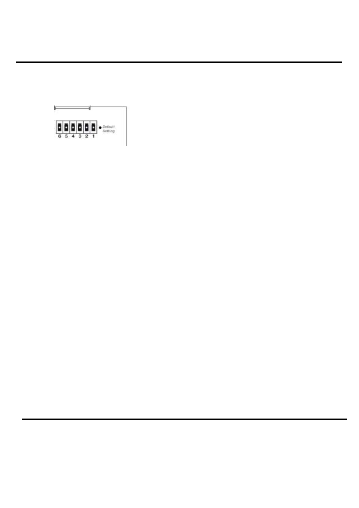
Restore button
There is a button hidden in the box for restoring the system factory default settings. When the
system fails to install or operates abnormally, use the included assistant stick in the package and
follow the following procedures to reset the system back to its original status.
Poke the assistant stick into the hole to press down on the restore button. Restart the system by
unplugging and re-plugging the power jack. While keeping the button pressed, the system will
perform POST twice rather than the usual once, which can be observed from the flashing LEDs.
After the system flashes the LEDs for the second time, withdraw the stick to release the button.
The system will have restored factory default settings at that moment.
Power adapter
Connect the power jack of the included power adapter. Connecting the power adapter should be
the last operation while physically installing Video Server.
Otros manuales para IPVS1A
2
Tabla de contenidos
Otros manuales de Servidor de 4xem


