Zero88 RigSwitch Manual de usuario

RigSwitch
Introduction
Revisions
Warnings & Safety
Installation
Connecting the mains
Connecting channel outputs
Control
DMX Control
DALI Control
iCANnet Control
Mixing Control Methods
Alarm Input
Mechanical
Support
RigSwitch is a remote controlled power switching solution suitable for any size venue, utilising Cooper Lighting
Solutions broad portfolio of power management technologies.
RigSwitch can be delivered in standard 12 or 24 channel cabinet configurations with RCD or RCBO options with a
wide choice of user control interfaces. Customised RigSwitch configurations include larger channel counts and options
for RCBO traffic lights and AFDD (Arc Fault detection). With individual relays rated for up to 32A operation RigSwitch
can cater for even the most power hungry user.
RigSwitch is ideal for switching power for todays’ modern entertainment lighting systems, including moving lights, hot
power sockets, specials and LED equipment.
Please read this manual before use, especially the Warnings & Safety section.
Zero 88 - RigSwitch - Page 1 of 16 Printed: 12/03/2021 11:03:15 ES

E&OE. Cooper Lighting Solutions reserves the right to make changes to the equipment and specificationdescribed
in this manual without prior notice.
Zero 88 - RigSwitch - Page 2 of 16 Printed: 12/03/2021 11:03:15 ES
Introduction
Thank you
Thank you for choosing RigSwitch by Zero 88 to fulfil your lighting power needs. We sincerely hope that your new unit
will bring you years of trouble free service. We make great efforts to build in reliability and serviceability at every stage
of our development and production processes and include a three-year limited warranty - giving you peace of mind for
your investment.
Our extensive dealer network can also provide you with technical service and sales support in your local language no
matter where you are in the world. If you have any questions, comments or problems our contact details can be found
at zero88.com/support
Once again, thank you for choosing Zero 88.
This manual
This online manual describes the operation of RigSwitch remote controlled power switching cabinets.
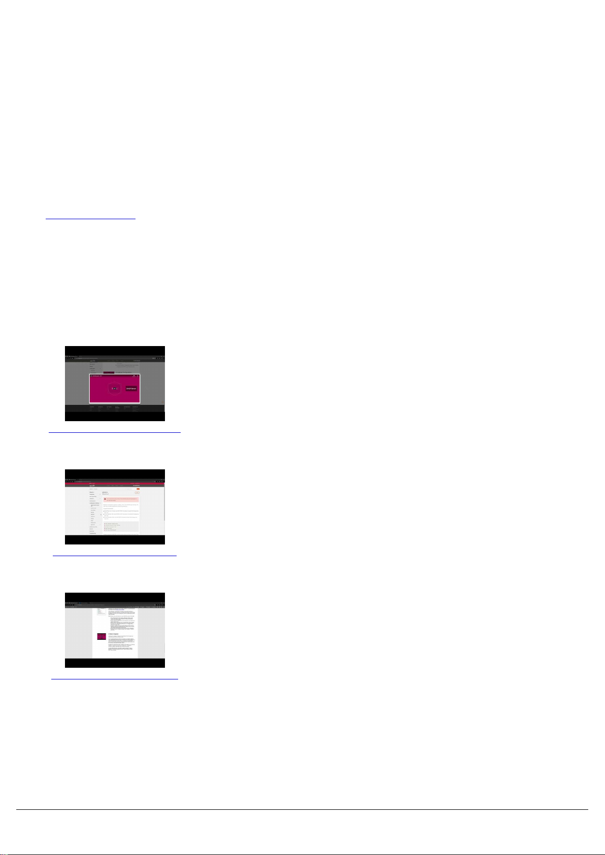
https://youtu.be/gvNuwCChcrg
For an overview of the Zero 88 Online Manuals, take a look at this
video.
https://youtu.be/Turfy1Ar_Kg
For detailed information on each function, the manual has been
divided into chapters - one for each major area, which can be
navigated using the menu on the left-hand side. You can also search
the manual using the search bar top right.
https://youtu.be/7BZsxnBjcno
Each section or whole chapters can be exported to PDF by tapping
"PDF", found just below the search bar. The whole manual can be
exported as a PDF, by tapping "PDF" at the top page of the manual.
Zero 88 - RigSwitch - Page 3 of 16 Printed: 12/03/2021 11:03:15 ES

Zero 88 online manuals are updated regularly to ensure you have all the relevant information and useful tips. Check
out the Revisions section to see what has been added. If you see something that doesn't look right, or have
Revisions
Jan 2021 - Manual created - ES
Zero 88 - RigSwitch - Page 4 of 16 Printed: 12/03/2021 11:03:15 ES

Warnings & Safety
Do not remove the covers without first completely disconnecting RigSwitch from the mains supply.
This product must be earthed.
This equipment is designed for professional stage lighting control and is unsuitable for any other purpose. It
should be used by, or under the supervision of, an appropriately qualified or trained person.
Zero 88 - RigSwitch - Page 5 of 16 Printed: 12/03/2021 11:03:15 ES

Installation
The unit should be installed in a dry ventilated location, where ambient temperature and humidity are within the
operating range of the unit.
RigSwitch cabinets are provided with four fixing holes for wall mounting. The mounting holes can be accessed by
undoing the screws on the front cover and removing it
Wall drilling positions are shown in the diagram below.
RigSwitch 12 cabinets have a height of 450mm (max 18kg)
RigSwitch 24 cabinets have a height of 600mm (max 20kg)
Zero 88 - RigSwitch - Page 6 of 16 Printed: 12/03/2021 11:03:15 ES

Connecting the mains
Zero 88 - RigSwitch - Page 7 of 16 Printed: 12/03/2021 11:03:15 ES

To connect the mains to RigSwitch cabinets, bring in a suitable 3
phase supply at 100A per phase maximum, to the main isolator top left
of the cabinet, and a secure mains earth to the Earth busbar at the top
of the cabinet. RigSwitch will accept a maximum 35mm2 input supply
cable.
Top Cable Entries
2x Flange:
14x ø11mm
8x ø15mm
2x ø28mm
Relief stamp:
2x M32/M40
Connecting channel outputs
Double stacked load output terminals for live and neutral per channel
are situated top right of the cabinet, and will accept a maximum 6mm2
cable. Earths will share the main bus bar top left of the cabinet.
Each block of 12 channels is rated at a maximum of 192A load.
Top Cable Entries
2x Flange:
14x ø11mm
8x ø15mm
2x ø28mm
Relief stamp:
2x M32/M40
Zero 88 - RigSwitch - Page 8 of 16 Printed: 12/03/2021 11:03:15 ES

Control
RigSwitch cabinets feature an SCMR1232 Relay Controller, which can be controlled with DMX, DALI or iCANnet.
RigSwitch 12 include one of these, and RigSwitch 24 include two.
Connecting and configuring the control methods...
DMX Control
DALI Control
iCANnet Control
DMX Control
Zero 88 - RigSwitch - Page 9 of 16 Printed: 12/03/2021 11:03:15 ES

RigSwitch cabinets feature an SCMR1232 Relay Controller, which can be controlled with DMX. RigSwitch 12 include
one of these, and RigSwitch 24 include two. To control with DMX, bring in a suitable DMX feed into the SCMR1232
RS485 terminals. If this SCMR1232 is the last device on the DMX line, terminate the DMX line with the termination
switch. If the SCMR1232 is not the end of the DMX line, whether that be the DMX line continuing to another device, or
to the other SCMR1232 in RigSwitch 24, continue the DMX the feed out of these terminals, and do not terminate.
The DMX start address of the SCMR1232 can be configured with the rotary encoders using a terminal screwdriver.
The SCMR1232 is a 12 channel device, with the first relay channel being controlled by the start address, and each
relay consuming a single sequential channel.
SCMR1232 will be defaulted to DMX address 1. The second SCMR1232 in RigSwitch 24 for channels 13-24, will be
pre-addressed to DMX address 13.
If the SCMR1232 is connected to an iCANnet network with iCANsoft present, individual relay channels can be
configured to individual DMX channels, rather than sequential blocks. To allow this functionality, configure the rotary
DMX address encoders to 0-0-0.
When DMX is present, the DMX/RS485 indicator LED will flash green.
DALI Control
Zero 88 - RigSwitch - Page 10 of 16 Printed: 12/03/2021 11:03:15 ES
Tabla de contenidos
Otros manuales de Unidad de distribución de energía de Zero88


