Zella DC Pro 12 Manual de usuario


1. Introduction
A Micro Data Centre is a stand-alone housing unit that replicates
all of the cooling, security and power capabilities of a traditional
data centre on a much smaller, lower cost scale. It miniaturizes the
data centre into the size of an average refrigerator, offering its own
cooling and power capabilities, signicantly reducing operational
and energy costs by 30-60%, and on-premise IT footprint. Moreover,
it allows for portability and can be moved from location to location
and expanded to a set of “modular’’ data centres as business
grows. Micro Data Centres are the perfect solution for companies,
which must house critical infrastructure in a quiet ofce amongst
personnel through to infrastructure-poor remote locations.
This guide needs to be followed according to the steps of
installation to ensure the most effective installation is achieved.

2. Safety Instructions
2.1 Overview
This manual contains instructions relating to safety, installation,
operation, maintenance and warranty of this product and its
components.
Please keep this manual in a safe place for future references.
Handling Safety
Do not lift heavy loads without assistance.
Important safety note
zCaution needs to be taken when removing the
side panels of the Micro Data Centre, in particular
when dealing with the 38U as they are heavy.
We recommend a 2 man lift when removing and
re-installing the side panels.
zALWAYS ENSURE the bottom brackets are locked in
and that the top pins are COMPLETELY slotted in.
zDon’t turn on the cooling system RCD until the
the wiring is completed between the Zella Pro and
external condenser.
<18 kg
32–55 kg
18–32 kg
>55 kg

3. Power Connection
3.1 Power Supply Requirements
Important note
DEPENDING ON SIZE AND MODEL. Power consumption can vary
from less than 10 amps and up to 60 amps depending on load.
When arranging the on-premise power supply with the landlord
or power company make sure you structure your energy bill
based on power used and not based on a xed power supply.
For security purposes we recommend a hardwired connection
directly into power source rather than a plug.
Max power supply to Zella Pro can either be 10, 32 & 60 amps
(220v – 240v / 50/60hz) depending on the model
WE RECOMMEND THAT INSTALLATION SHOULD ONLY
BE CARRIED OUT BY SUITABLY QUALIFIED ELECTRICAL
CONTRACTOR WITH THE NECESSARY TRAINING.
3.2 Switchboard Operation
Following the connection to mains power
DEPENDING ON MODEL THE SWITCHBOARD LAYOUT AND
CONFIGURATION IS DIFFERENT. (SEE LAYOUT DIAGRAMS –
pages 6-9)
Start Up Procedure
zSwitch Mains Isolator switch to the ON position
zVery Important - Leave the Cooling System circuit breaker in
the OFF position – Electrical Hazard
zPlease Note: If hardwiring 6 or 8KVA UPS – LEAVE IN OFF
POSITION until UPS and switchboard have been connected
by electrician – Electrical Hazard. (See UPS Manual)
zSwitch UPS to the ON position once connected
zImportant - (Leave the RCD cooling and Cooling system for
the air conditioner contractor – Electrical Hazard)
3. Power Connection
3.3 Power Supply diagram to PDU switchboard
Non-monitored sockets
UPS Power
Cooling system
Cooling system
RCD
Mains power

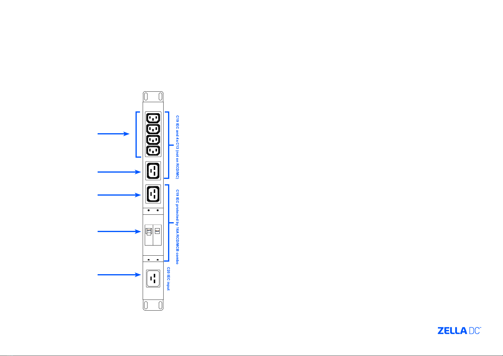
3. Power Connection
3.4 Switchboard layout
Front View
Rear View

4. Access Control
4.1 Metal Key Pad Operation
The default code for the doors are pre-set in the factory
as follows:
zFront door - 2580
zBack door – push button
FOR FURTHER INSTRUCTION TO PROGRAM DOOR
CODES. SEE USER MANUAL
4.2 Biometric / Card Reader
The Zella Pro is supplied with a default card which will
open the front door. The rear door is opened by the push
button located inside the Zella Pro.
See user manual for programming options. Use card
reader until you are ready for biometric access mode.
4.3 L.E.D. Key Pad Operation
The default code for the doors are pre-set in the factory
as follows:
zFront door – 2580#
zBack door – push button
FOR FURTHER INSTRUCTION TO PROGRAM DOOR
CODES. SEE USER MANUAL
Front panel description
Card reader
Fingerprint reader
Key Pad
Card reader
3x4
Matrix
Keypad
Case Screw
Bell Button
(with BL-D40)
Antenna
(AC-Q42&AC-Q44 only)
Door
Indicator
Mode
Indicator

5. Single & Dual Cooling System Commissioning Steps
Important Safety Warning
BEFORE PLUGGING THE EXTERNAL CONDENSER POWER CABLES
(ORANGE AND GREY) TO THE BACK OF THE ZELLA PRO. ENSURE
THE COOLING SYSTEM RCD IS OFF ON THE BASE MOUNTED
SWITCHBOARD
You also have the option to unplug the cooling system/s power
cables from the back of the switchboard during the commissioning
process
PLEASE ENSURE THERE IS POWER TO THE Zella Pro
(SWITCHBOARD) BEFORE COMMISSIONING THE COOLING SYSTEM
5.1 Condenser
Depending on the model and cooling capacity the condenser
maximum distance can vary between 20 and 30 meters. The Zella
Pro is supplied with relevant cable length (3 core orange output
to condenser & 4 core grey cable. The condenser draws its power
from the Zella Pro. The condenser size and weight can also vary
depending on model and cooling capacity. The condenser will be
positioned either on the outer wall of the building or on the roof.
5.2 Commissioning
Once the Zella Pro has been positioned in its proposed location and
connected to power the air conditioning contractor can commission
the cooling system.
Only once the air conditioning contractor has Connected wires to
the condenser and plugged the grey and orange cable into the Zella
Pro, can the cooling be turned on.
ENSURE THE COOLING SYSTEM PLUG IS PLUGGED INTO THE
CORRECT POWER SOCKET ON THE SWITCHBOARD
5.3 Wiring
The Zella Pro is supplied with all the cables (orange and grey)
which is pre-coiled and ready to be run with the copper piping
during the commissioning process. The pre-coiled condenser
cables are located inside the Zella Pro.
CONTRACTORS TO ENSURE BOTH ORANGE AND GREY CABLES
ARE LOCKED BY TURNING THE YELLOW DISK ON THE SIDE OF THE
CABLE PLUGS WITH A SCREW DRIVER. THE AIR CONDITIONING
CONTRACTOR MUST SUPPLY THEIR OWN COPPER PIPING.
WIRING TABLE (WHITE CABLE)
1 - Live Red / Brown
2 - Neutral Blue / Black
3 - Signal White
Green / Yellow Earth / Ground
WIRING TABLE (ORANGE CABLE)
1 - Live Red / Brown
2 - Neutral Blue / Black
Green / Yellow Earth / Ground

5. Single & Dual Cooling System Commissioning Steps
5.3 Wiring cont.
Electrical Hazard – Ensure cooling system is in the OFF position on
Zella Pro base mounted switchboard and orange cooling system
plug is unplugged from rear of switchboard
Grey cable termination in condenser
(supplies power back to the Zella Pro)
(4 core cable)
1 – Brown
2 – Blue
3 – White
- Green / Earth
Orange cable termination in condenser
(supplies power to the external condenser)
(3 core cable)
L – Red
N – Blue
- Green / Earth
Este manual sirve para los siguientes modelos
2
Tabla de contenidos
Manuales populares de Almacenamiento de otras marcas


Spectra Logic
Spectra Logic T-Series Spectra T50e Manual de usuario

Panasonic
Panasonic LKM-F931-1 Manual de usuario

Tabernus
Tabernus Enterprise Erase E2400 Manual de usuario

Rocstor
Rocstor COMMANDER 3F series Manual de usuario

HP
HP P9000 Manual de usuario

Western Digital
Western Digital Ultrastar Data60 Manual de usuario