ZCS Robotics Marlin Manual de usuario


045BA0 - MARLIN
5045BA0 - MARLIN
5045DE0 - MARLIN Power
5045EL0 - MARLIN Super Power
IT La sigla di identificazione del robot è riportata sulla targhetta applicata sul pannello frontale. Sulla base della sigla, è possibile
individuare, nella tabella riportata a piè di pagina, la denominazione commerciale del robot.
EN The identification code of the robot can be found on the plate on the front panel. On the basic of the code you can find the trade name of
the robot in the table at the bottom of the page.
FR Le sigle d’identification du robot est reporté sur la plaque appliquée sur le panneau avant. En se basant sur le sigle, il est possible
d’identifier la dénomination commerciale du robot dans le tableau se trouvant au bas de la page.
DE Das Typenschild mit der Kennnummer des Roboters befindet sich auf der vorderen Abdeckung des Gerätes. Anhand der Kennung kann
die Handelsbezeichnung des Roboters mit Hilfe der Tabelle am Seitenende festgerstellt werden.
ES La abreviatura de identificación del robot se indica en la placa aplicada sobre el panel frontal. En base e esa abreviatura es posible
identificar, en la tabla indicada en el fondo de la página, la denominación comercial del robot.
NL Het kenteken van de robot bevindt zich op het identificatieplaatje op het frontpaneel. Aan de hand van dit kenteken kan de commerciële
benaming van de robot in de tabel onderaan de bladzijde teruggevonden worden.
DA På frontpladen er de en model-kode på robotter. På baggrund af koden er det muligt at identificere det kommercielle navn på robotten, i
tabellen, i bunden af siden.

1
User manual
EN
MD-CT-RO-31-R4.0 - EN - 03-2015
OVERVIEW
General information. ......................................................................................................................................................................2
Introduction. ...................................................................................................................................................................................2
Purpose of the manual...................................................................................................................................................................2
Identication of manufacturer and equipment................................................................................................................................3
Requesting technical assistance....................................................................................................................................................3
Safety information..........................................................................................................................................................................3
Technical information. ...................................................................................................................................................................4
Technical specications..................................................................................................................................................................4
Main parts. .....................................................................................................................................................................................5
Installation and unpacking. ...........................................................................................................................................................6
Unpacking. .....................................................................................................................................................................................6
Installation......................................................................................................................................................................................6
Installation of charging base. .........................................................................................................................................................6
Positioning the robot in the charging base...................................................................................................................................10
Use and operation. .......................................................................................................................................................................11
Requirements for use...................................................................................................................................................................11
Navigation. ...................................................................................................................................................................................11
Settings - programming mode......................................................................................................................................................12
Setting - working times.................................................................................................................................................................13
Settings - language options..........................................................................................................................................................13
Settings - diagnostics...................................................................................................................................................................13
Settings - statistics. ......................................................................................................................................................................13
Set up...........................................................................................................................................................................................13
Using the communication box......................................................................................................................................................14
Ordinary cleaning.........................................................................................................................................................................14
Prolonged inactivity and restarting...............................................................................................................................................16
Troubleshooting guide.................................................................................................................................................................17
Troubleshooting. ..........................................................................................................................................................................17
Replacement of parts...................................................................................................................................................................18
Tips on replacing parts.................................................................................................................................................................18
Battery replacement.....................................................................................................................................................................18
Robot disposal. ............................................................................................................................................................................18
Reproduction, even partial, of this document without written permission by the manufacturer is strictly forbidden. The
manufacturer assumes a policy of continual improvement and reserves the right to modify this document without prior notice
on condition that the changes do not constitute health and safety risks.
© 2008 – Texts, illustrations and page layout: Tipolito La Zecca. The text may be reproduced, in whole or in part, on condition
that the author is mentioned.

2
User manual
EN
GENERAL INFORMATION
INTRODUCTION
Congratulations on purchasing this product, which we are certain will meet your needs and expectations. This project was
created by ZUCCHETTI CENTRO SISTEMI S.p.A. (UNI EN ISO 9001 certied company), a software house that since 1982
has consolidated its activities and presence on the international market. Applying advanced IT solutions in the eld of industrial
automation means optimising the production activities and simplifying the work procedures. This product was created on the basis
of on-going research by ZUCCHETTI’s laboratories.
PURPOSE OF THE MANUAL
• This manual forms an integral part of the appliance and was produced by the Manufacturer to provide the necessary information
to people authorised to interact with it during its working life.
• Operators of the appliance must adopt correct working practices and must carefully read and follow all the instructions
contained in this manual.
• This manual was written by the Manufacturer in the original language of Italian and may be translated into other languages to
meet legal and/or commercial requirements.
• Carefully read the instructions contained in this manual to avoid any unnecessary risks to people’s health and safety, as well
as economic damages.
• Keep this manual in a safe and easily accessible place for quick reference.
• Some information and illustrations contained in this manual may not perfectly correspond with the appliance in your possession;
however, this will not affect its functioning.
• The Manufacturer reserves the right to make changes at any time, without notice.
• The following symbols are used throughout this manual to highlight some particularly important information or identify some
important specications.
Danger - Attention
Thissymbolindicatessituationsinvolvingimminentdanger,which,ifignored,couldputpeople’shealthand
safety at risk.
Warning - Caution
This symbol indicates situations where it is necessary to behave in a certain way in order to avoid putting
people’shealthandsafetyatrisk,andtoprotectthedevice.
Important
Thissymbolidentiesparticularlyimportanttechnicalinformationthatmustnotbeignored.
3
User manual
EN
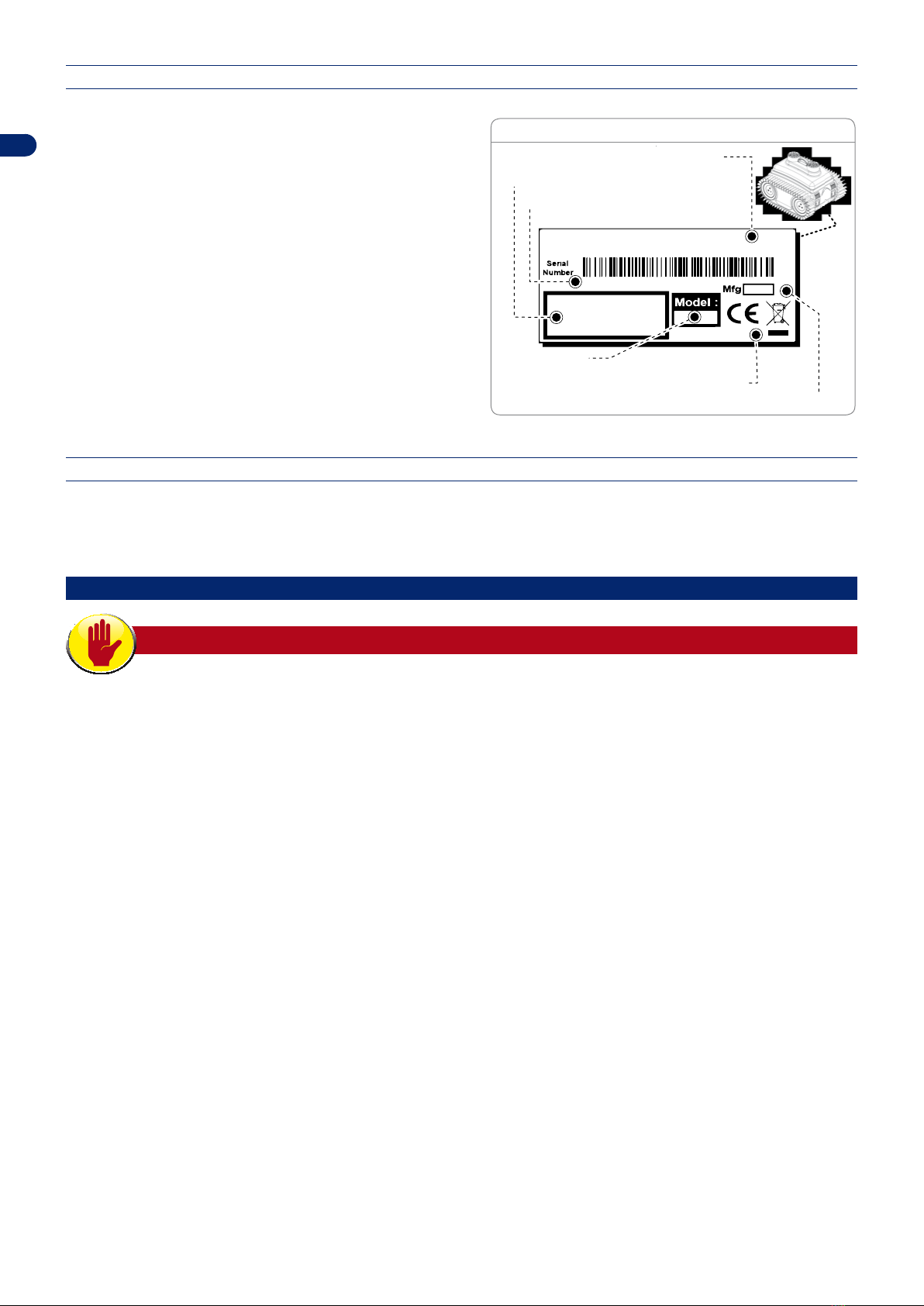
IDENTIFICATION OF MANUFACTURER AND EQUIPMENT
The identication plate shown here is applied directly onto
the appliance. It contains references and all the information
essential for the safe operation of the device.
A. Name of manufacturer.
B. CE conformity label
C. Model / serial number / manufacturing year.
D. Technical specications: voltage, current, protection rating,
mass.
Zucchetti Centro Sistemi S.P.A
Via Lungarno 305/A - 52028 Terranuova B.ni (AR)
0000
00000000000000000
00000000000000000
(C) Manufacturing year
(C) Model
(B) EC conformity label
(A) Name of manufacturer
(D) Technical specifications
(C) Serial number
DATA PLATE
REQUESTING TECHNICAL ASSISTANCE
For any technical requirements, please contact the Manufacturer’s Technical Service Centre or an authorised dealer. For technical
assistance, please indicate the data reported on the identication plate, the approximate hours of use and the type of fault
detected.
SAFETY INFORMATION
SAFETY RULES
• During design and construction, the manufacturer carefully considered the possible hazards and personal risks that may result
from interacting with the equipment. In addition to complying with the applicable laws in force, the manufacturer adopted all
the “good manufacturing practice regulations.” The purpose of this information is to inform users on the need to use extreme
caution to avoid risks.
• Before use, carefully read the whole manual and be sure to understand it fully, especially the safety information.
• Only use the equipment for the purposes specically intended by the manufacturer. Improper use of the equipment may
be hazardous to personal safety and health and may lead to economic losses. Keep in mind that the operator or user is
responsible for accidents or danger to other people or their property.
• This appliance cannot be used by people (including children) with limited physical, sensorial or mental abilities and little
experience and/or know-how, unless they are supervised by a person responsible for their safety or have received instructions
on how to use the appliance. Children should be supervised to ensure that they do not play with the appliance.
• If the power supply of the transformer is damaged, it must be replaced by the manufacturer or by its technical service centre
or by a person with similar qualications, in order to avoid any risk.
• Always position the power supply unit at a minimum distance of 3 metres (10 feet) from the edge of the pool, in a dry, well-
ventilated area. Position the power supply unit in an area that cannot be reached by children. For example, at a height above
160 cm (63 inches).
• Never remove, bypass or tamper with the safety devices installed. The failure to comply with this requirement may pose
serious risks to the health and safety of people.
• Operators who perform repairs during the working life of the robot must have the necessary technical expertise, skills and
experience in this specic eld. The failure to comply with these requirements may be hazardous to the health and safety of
people.
• Any work to be performed on the charging station must be carried out with plug of the power cord disconnected.
• The robot cannot be used without the top cover. If the mechanical parts of the robot are damaged, replace them.

4
User manual
EN
• The Manufacturer shall not be held liable if unoriginal spare parts are used.
• Never use and recharge the robot in explosive and/or ammable environments.
• Only use the battery charger and power supply unit supplied to recharge the robot. Improper use can cause electric shocks,
overheating or leakage of corrosive liquid from the battery. In case of leakage, the battery must be washed with water/
neutraliser; in case of contact with eyes, consult a physician.
TECHNICAL INFORMATION
TECHNICAL SPECIFICATIONS
Description Model
045BA0 5045BA0 5045DE0 5045EL0
Maximum pool lenght Mt 25 12 25 50
Robot dimensions (W x
H x D) mm 410 x 320 x 460
Weight Kg 21
Ambient operating
temperature Max °C
ROBOT 5°(Min) +35°(Max)
BATTERY CHARGER -10°(Min) +40°(Max)
Water protection class IP
ROBOT - IP68
BATTERY CHARGER - IP64
Maximum pool depth Mt 10
Maximum recharging
base depth Mt 5
Water, operating
parameters
pH: 7.0-7.8
Temperature: 5-35°C
NaCl Max: 5,000 ppm
Chlorine Max : 4 ppm
Power Supply unit
Vin 100 - 240Vac.
Input Frequency
range 50-60.
Vout 36Vcc - 8,9A.
Vin 100 - 240Vac.
Input Frequency
range 50-60.
Vout 30Vcc - 6,2A.
Vin 100 - 240Vac.
Input Frequency
range 50-60.
Vout 36Vcc - 6,7A.
Vin 100 - 240Vac.
Input Frequency
range 50-60.
Vout 36Vcc - 8,9A.
Battery Lithium Ion - 25,2V -
13.8Ah Lithium Ion - 25,9V - 13.75Ah
Avg. working time hh:mm 2:00
Avg. recharging time hh:mm 3:00 3:30 2:30 1:45
Travelling speed on the
bottom Mt/min. 10 - 20 8 - 12 12 - 16 16 - 20
Travelling speed on the
wall Mt/min. 8
Filters 2 Litres, mesh pitch of 0.5mm
Tablet/Console included
Communication Box optional
Smooth wall kit optional
Adapter for curves
between the wall and
bottom
optional
5
User manual
EN
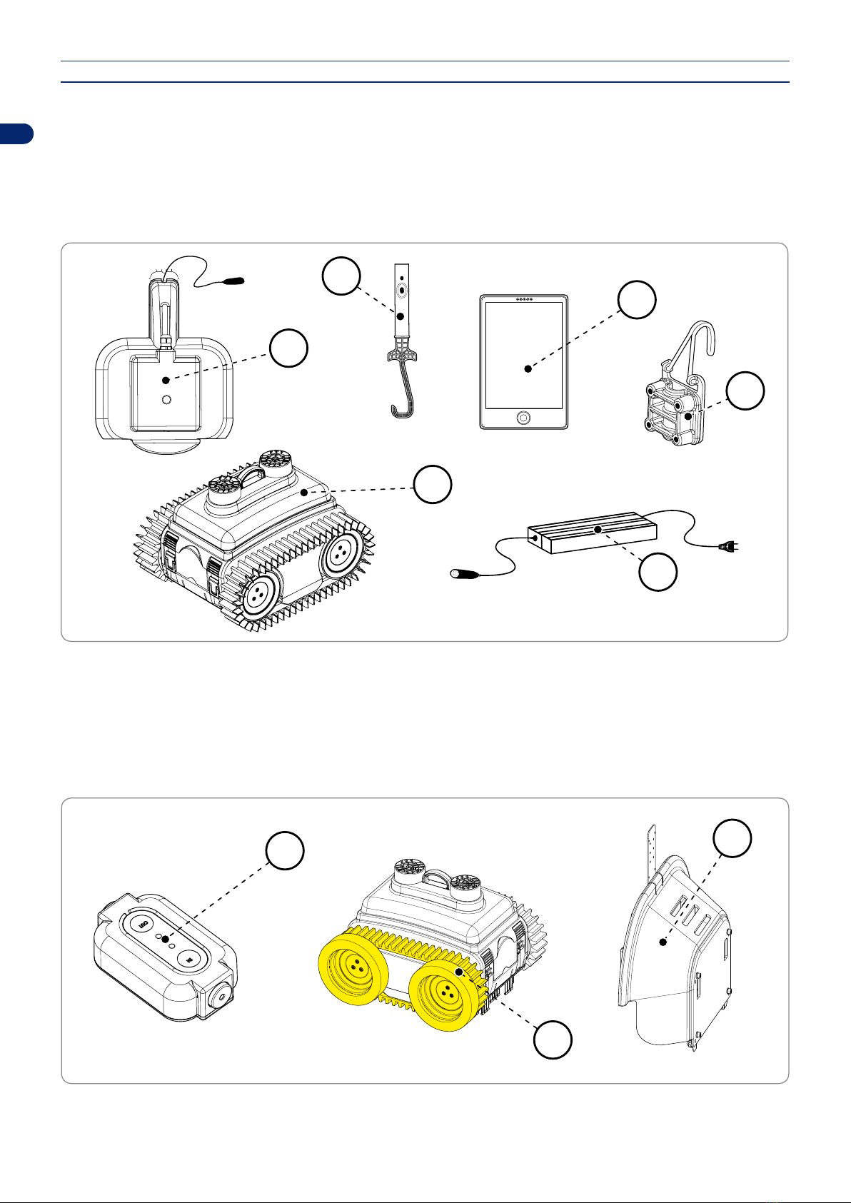
MAIN PARTS
1. Robot.
2. Robot hook: for lifting the robot out of the water (pole not included).
3. Charging hook: for securing the charging cord immersed in the water.
4. Robot recharger: for recharging the robot in the water.
5. Power Supply unit: powers the recharging of the robot.
6. Tablet/Console: it allows you to programme the robotic cleaner settings and consult the user manual.
4
1
6
2
3
5
7. Communication Box: Not included in the kit. Device to be installed between the power supply unit and robotic cleaner
recharging base. It allows you to recall the robotic cleaner to the recharging base or enable it to operate even if it is not within
the set working time band.
8. Smooth wall kit: Not included in the kit. Kit to be applied to the wheels in the presence of smooth walls which prevent the
robotic cleaner from climbing up them.
9. Adapter for curves between the wall and bottom: Not included in the kit. Allows the installation of the robotic cleaner
recharging base in swimming pools that are curved between the wall and bottom, distancing the recharging base up to 20 cm
from the wall so it can detect the bottom. The adapter also allows you to manage non-horizontal bottoms.
7
8
9
6
User manual
EN
INSTALLATION AND UNPACKING
UNPACKING
The equipment is delivered suitably packaged. When unpacking, carefully remove and check the integrity of the parts.
The packaging contains all the necessary information for handling the device.
INSTALLATION
• Remove the robot from the packaging.
• Place the robot on the ground.
• Install the charging base and then gently immerse the robot in the pool. Wait until it has settled on the bottom and then, using
the hook provided, place the robot near the charging plate from the front side of the robot, which is identied by a recharging
sticker. If positioned correctly, the leds of the recharger will light up continuously.
• Recharge the robot for 15 minutes before moving to the programming phase.
• To program the robot, take it out of the water using the hook provided, place it on the ground and follow the programming
instructions. The programming only works with the robot out of the water.
• Once programmed, immerse the robot in the water so that the work cycle can begin.
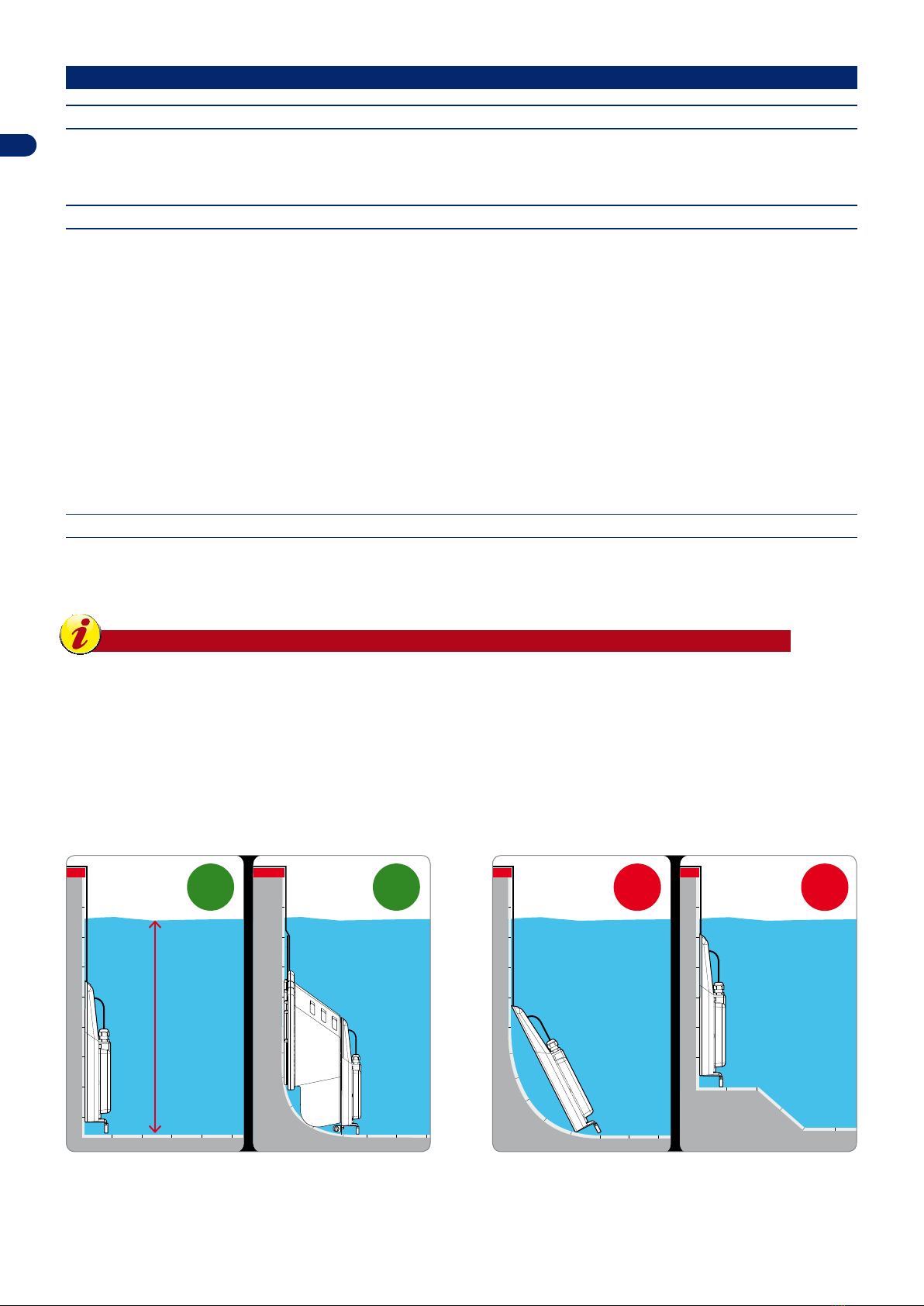
INSTALLATION OF CHARGING BASE
Remove the charging base from its packaging.
Place the charging base along the vertical wall of the pool.
Important
- Position the steel side of the dissipator in contact with the pool wall.
- Do not position the charging base on the bottom of the pool.
- Make sure that the angle formed between the charging base and the opposite bottom is 90° and that the
area surrounding the recharger (at least 2 meters) is even and horizontal. Alternatively, use the provided
adapter for curves between the wall and bottom.
- Preferably position the charger on the deeper end and, however, at a depth not greater than 5 meters.
Max. 5 mt
OK OK
NO NO

7
User manual
EN
Here are some examples of where the charging base can be installed and where it cannot be installed:
1. position the wire of the charging base 30 cm from the
corner of the wall. Alternatively, the charger can be
installed at the centre of the wall. In this type of set-up,
there are three positioning options and distances:
-At least three meters away from the left side wall. Set
the mode of re-entry to follow the edge in a clockwise
direction.
-At least three meters away from the right side wall. Set
the mode of re-entry to follow the edge in a counter-
clockwise direction.
-Roughly in the centre, recommended for irregular-
shaped or round pools, or pools with narrow passages,
and when the above rules cannot be followed. Set the
Random re-entry mode.
Left
Left
Centre
Centre
LeftCentreRight
Right
Centre Right
OK
30cm
30cm 30cm
≥ 300 cm
2. in case of bottoms with level differences or steps, place
the charging base on the opposite wall. Observe the
above-mentioned distances.
3. do not place the charging base under or near a ladder.
Left
Left Centre
LeftCentreRight
Right
OK
30cm
30cm 30cm
NO
4. do not place the robot near steps. The robot may nd it
difcult to return to the charging base.
5. do not place the charging base on the wall near a level
difference.
NO
NO
8
User manual
EN
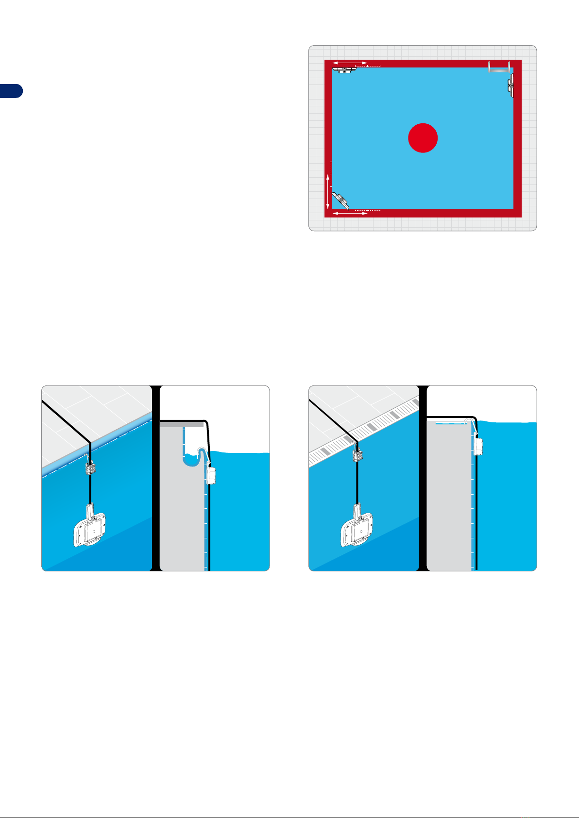
6. do not place the wire of the charging base less than 30 cm
from the corner. Do not place the recharging base in the
angle of the walls. It must be installed in contact with one
of the vertical walls of the swimming pool. Do not place the
recharging base under or near the stairs.
NO
In the event that more than one positioning solution is possible, follow these tips:
-Centre. This positioning is recommended for very irregular-shaped and round pools or pools with narrow passages.
-Left. This positioning is recommended for regular-shaped pools with left wall adjacent to the charger that forms a right angle.
-Right. This positioning is recommended for regular-shaped pools with right wall adjacent to the charger that forms a right angle.
After positioning the charging base, fasten the cord to the edge of the pool.
Here are some examples of pool edges with installation of the charging hook. The cord can be installed along the edge or on the
ground next to the pool, as long as there is an eyelet or a loop in each of these points on which to fasten the hook.
Este manual sirve para los siguientes modelos
1
Tabla de contenidos


