Your Solar Home SolarSheat Manual de usuario
SolarSheat Wall Installation
Manual
Version 1.5
April 23, 2013
Copyright 2013 Your Solar Home, All Rights Reserved
SolarSheat products must be installed in accordance to all local building, plumbing, electrical, and safety
codes. Your Solar Home (YSH) does not warranty any installations that are not performed by an
authorized YSH dealer/installer. YSH does not warranty any installations that do not use the
recommended mounting hardware and mounting guidelines contained in this technical manual.

SolarSheat and Interior Wall Fan Assembly Manual Version 1.5 2
1.0 INTRODUCTION TO SOLARSHEAT AND SOLAR AIR HEATING
The SolarSheat 1000GS & 1500GS solar collectors are designed to provide supplemental room heating
through forced hot air exchange. SolarSheat thermal collectors are fully modular and allow for series or
parallel connection as required by large spaces or multi-room heating requirements. The SolarSheat
uses energy from the sun to heat household air by circulating it through the collector, refer to the figure
1.1 below for a typical single-panel wall mounted configuration.
The “GS” series collectors are modular and can be connected together (up to three units), while
the GS does not include a PV module or fan and is intended for use with a DC fan assembly unit,
DC or AC inline fan or AC blower in larger installations.
Figure 1.1: Typical wall for SolarSheat
Every SolarSheat model is SRCC OG 100 Certified and features an
All-aluminum construction, designed to withstand harsh weather exposure.
The SolarSheat is designed to withstand typical snow and wind loading in
Accordance to CSA-F378.

SolarSheat and Interior Wall Fan Assembly Manual Version 1.5 3
The SolarSheat can achieve thermal conversion efficiencies in upwards of 50%, meaning that for every
square meter of collector area, the SolarSheat can produce roughly 500W of thermal energy on a clear
and sunny day:
* Measured for single collector setup, results may vary depending on collector arrangement and fan choice
Refer to Figures 1.2 to 1.5 for collector performance data at 0 deg Celsius:
Figure 1.2: Delta Temperature @ 0 Cels Figure 1.3: Collector Efficiency
Figure 1.4: “GS” Series Airflow (CFM) Figure 1.5: “GS” Series Airflow (m^3/hr)
1 m2of COLLECTOR AREA* = 500W of HEAT
11 ft2of COLLECTOR AREA* = 1750 Btu of HEAT

SolarSheat and Interior Wall Fan Assembly Manual Version 1.5 4
The SolarSheat wall installation system ships with a framed 12 V - 15W PV amorphous
module with 11.5 ft wiring harness, fan plate with 12 volt –15 W DC brushless fan
attached, wiring harness, sensor, 5” round snap lock duct, grommet, two terminal
connectors, hardware for assembling and power adapter attached. These components also
ship inside the new SolarSheat Fan Duct Kit.
You will need to unpack the separate Sun Force PV cell. Mounting hardware is provided
for attaching the PV cell to a wall or roof.
About this manual
There are three steps to successful installation of the SolarSheat.
They are:
Step 1 –Drilling the holes and preparing for the wall for installation of the SolarSheat
Step 2 –Installation of the fan assembly
Step 3 –Installing the SolarSheat collector.

SolarSheat and Interior Wall Fan Assembly Manual Version 1.5 5
Tools Required for Installation
You will require the following tools to complete the SolarSheat and fan assembly installation.
Safety Glasses
Drill
Hole Saw 5” or Jig Saw
Measuring Tape
Level
Wire Cutters
Fish Tape
Pliers for crimping
Robertson #2 screw bit
3/16” hex head driver for attaching the Tek screws to the mount
¼” hex head driver for securing the white head screws to the diffuser plate
21/64” ” Drill bit (for drilling the grommet hole)
1/4” Drill bit (for seating the plugs in the fan assembly)
Hammer or rubber mallet
Silicon (not essential)
Drill with hexhead socket driver
Ladder
Vaccum
SolarSheat and Interior Wall Fan Assembly Manual Version 1.5 6
Step 1
Drilling the holes for the SolarSheat collector
WALL MOUNT INSTALLATION INSTRUCTIONS
(For roof mount, please refer to SolarSheat Roof Mount Installation Manual)
Note: Make sure the distance of the overhang or eve is 1.5 X the distance to the top of the collector.
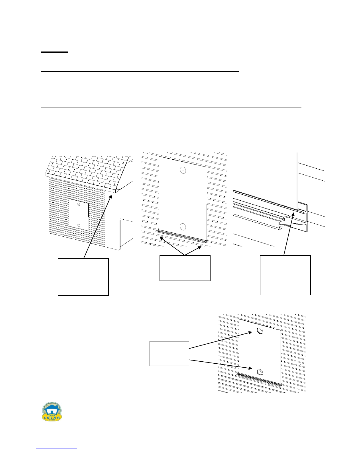
1. Locate un-shaded portion of the building for collector placement
2. Using a level and the included template, mark the location of the bottom mounting rail and
intake & exhaust duct locations. Be sure to avoid wall studs and electrical wire
3. Cut 5” holes through the building wall using a hole saw
or jig saw.
Center the bottom
mounting rail on the
template
5” Holes drilled
through wall
Level out the
template on the wall.
Be sure to avoid
shading from
overhanging eave
Mark the position of
the bottom rail by
resting template on
rail ledge

SolarSheat and Interior Wall Fan Assembly Manual Version 1.5 7
Step 2
Installation of the Fan Assembly
Note: The holes for the collector must be drilled(Step 1) first before you can install the fan
assembly. Use the template that ships with the collector and refer to the Collector
Installation at the top of the manual.
The next step is to install the fan assembly plate on the inside wall of where you want the
exhaust and heat. The fan assembly can be installed on any outside wall. For roof or ceiling
mounts, continue to use our DC inline fan (part #1015), AC inline fan (Part #1021) or Fan Box
(Part #1174).
The fan assembly comes with a two harnesses attached(above). One has as a piece of thermostat
wire that you will need to attach the sensor. The second harness is for the power source (PV
panel) that is run around the outside of the snap lock duct and in behind the plastic 5 inch collar
on the outside of the wall.

SolarSheat and Interior Wall Fan Assembly Manual Version 1.5 8
1. Cutting the inside wall for the fan plate
Use the back side of the metal fan assembly and trace the outside. (you can also measure the
inside flange. Make sure you mark the inside of each tab. (Do not cut the outside template of
the tab or else you won’t have any wall to mount the plate.) That is going to be where the
plate ends and the tab is inserted in the wall.
2. Use a pencil to mark each tab and where the bend is located. You will need a jig
saw, sawzall or small hand saw to cut the wall. Use a 3/8 drill to start the hole before
you cut. Mark the holes for the plate where the plugs and screws to hold in place as
well. You will need a 1/4 inch drill bit for the plugs.
Mark here for
cut out

SolarSheat and Interior Wall Fan Assembly Manual Version 1.5 9
The photo below illustrates cutting the template out of the wall before the holes were drilled in
the wall.
Remember the plate will cover the rough edges of the hole and cutout so you won’t see any of
the edges. Use a vacuum to remove the debris from the wall. Note: (the foam inside the wall in
this picture is a SIP (structural insulated panel) and is a non standard wall (used for
demonstration).

SolarSheat and Interior Wall Fan Assembly Manual Version 1.5 10
3. Drilling the snap lock duct
You will be required to drill the piece of snap lock duct that comes with the kit so that a grommet
can be inserted. Measure the piece of the snap lock that will fit your inside wall. Cut with shears.
There is a 10 inch piece provided.
4. Trim the snap lock and insert the grommet to the desired size and drill a hole with
a 21/64” drill bit or something close to the size to allow for the grommet.
Insert the grommet into the snap lock material.
5. Close the snap lock and position over the collar on the fan assembly. Insert the
sensor wire through the outside middle of the snap lock material and pull through the
centre. See below.
Tabla de contenidos


