Wisi MICRON MyM Pro Manual de usuario
MyM Pro MICRON Installation Guide
www.wisi.se

TABLE OF CONTENTS
1. INTRODUCTION 3
2. UNPACKING THE UNIT 4
3. CONNECTIONS AND INDICATIONS 5
4. IP SETTINGS 6
4.1 TCP/IP settings for Windows XP . . . . . . . . . . . . . . . . . . . . . . . . . . . . . 6
4.2 Connecting your PC to the MyM Pro MICRON . . . . . . . . . . . . . . . . . . . . . . 7
4.3 Settings of IP address . . . . . . . . . . . . . . . . . . . . . . . . . . . . . . . . . . . 7
5. MENUES AND SETTINGS 8
5.1 Overview menu. . . . . . . . . . . . . . . . . . . . . . . . . . . . . . . . . . . . . . 8
5.2 Input settings. . . . . . . . . . . . . . . . . . . . . . . . . . . . . . . . . . . . . . . 9
5.2.1 DVB-T/T2 reception . . . . . . . . . . . . . . . . . . . . . . . . . . . . . . . . . . . . . . . . . . . . . . . . . . . . . . . . . 9
5.2.2 DVB-S/S2 reception . . . . . . . . . . . . . . . . . . . . . . . . . . . . . . . . . . . . . . . . . . . . . . . . . . . . . . . 10
5.2.3 DVB-C reception . . . . . . . . . . . . . . . . . . . . . . . . . . . . . . . . . . . . . . . . . . . . . . . . . . . . . . . . . . 10
5.2.4 IPTV reception . . . . . . . . . . . . . . . . . . . . . . . . . . . . . . . . . . . . . . . . . . . . . . . . . . . . . . . . . . . . 11
5.3 Output settings . . . . . . . . . . . . . . . . . . . . . . . . . . . . . . . . . . . . .12
5.3.1 Modulation . . . . . . . . . . . . . . . . . . . . . . . . . . . . . . . . . . . . . . . . . . . . . . . . . . . . . . . . . . . . . . 12
5.3.2 Decoder settings . . . . . . . . . . . . . . . . . . . . . . . . . . . . . . . . . . . . . . . . . . . . . . . . . . . . . . . . . . 13
5.3.3 Decoder status . . . . . . . . . . . . . . . . . . . . . . . . . . . . . . . . . . . . . . . . . . . . . . . . . . . . . . . . . . . 14
5.3.4 Modulator settings . . . . . . . . . . . . . . . . . . . . . . . . . . . . . . . . . . . . . . . . . . . . . . . . . . . . . . . . 14
5.4 Service Management . . . . . . . . . . . . . . . . . . . . . . . . . . . . . . . . . . .15
5.5 CI menu . . . . . . . . . . . . . . . . . . . . . . . . . . . . . . . . . . . . . . . . .16
5.6 System options . . . . . . . . . . . . . . . . . . . . . . . . . . . . . . . . . . . . . .16
6. INSTALLATION & CONFIGURATION 19
7. TECHNICAL SPECIFICATION 20
8. DECLARATION OF CONFORMITY 21
9. ABBREVATIONS 22

INTRODUCTION 3
1. INTRODUCTION
Thank you for purchasing a WISI Norden product. The MyM Pro MICRON is a revolutionary solution for
reception and modulation both from satellite, terrestrially or IP transmitted TV content into an analogue
format suited for small SMATV networks where cost efficiency and high quality is required.
The MyM Pro MICRON has a multifunctional tuner that receives DVB-S/S2, DVB-T/T2, DVB-C and IP
transmissions.
The MyM Pro MICRON unit is delivered with hardware and software that supports MPEG-2/MPEG-4
decoding, HD downscaling, DOLBY decoding, DSB RF modulation with NICAM or A2 audio, IP control
and management.
The MyM Pro MICRON can be upgraded for enhanced functionality by software upgrades. Future
software upgrades will be available from web site.
WISI Norden AB
Phone: +46 (0)13 21 09 00
E-mail: [email protected]
Visit our web site www.wisi.se for more information.
UNPACKING THE UNIT 4
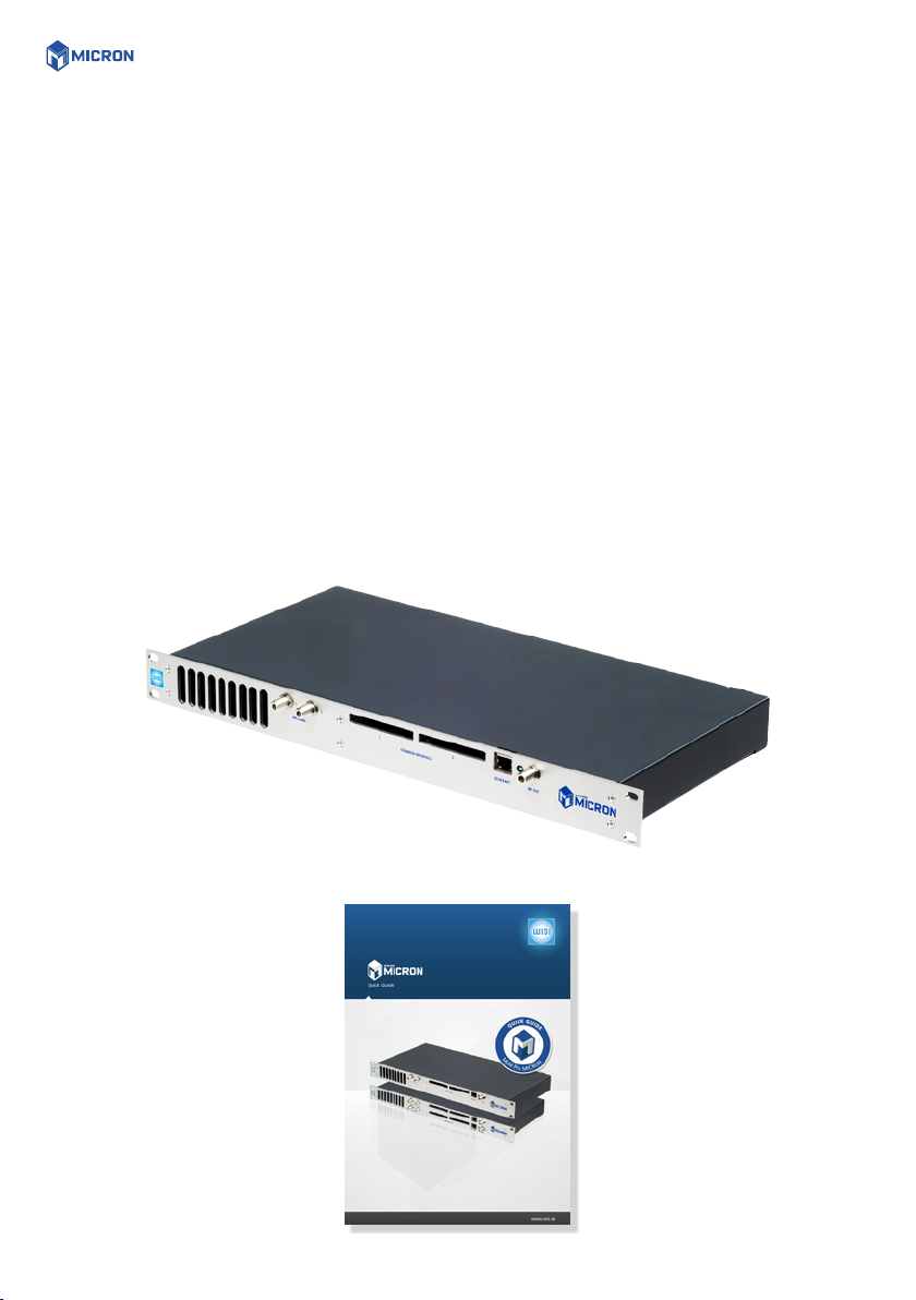
2. UNPACKING THE UNIT
The following items are included in the package:
Every unit is quality controlled by us before delivery. Should any items be missing when unpacking,
please contact our support service (see page 3 for contact info).
Amount
1
1
Description
MyM Pro MICRON
Quick Giude
CONNECTIONS AND INDICATIONS 5
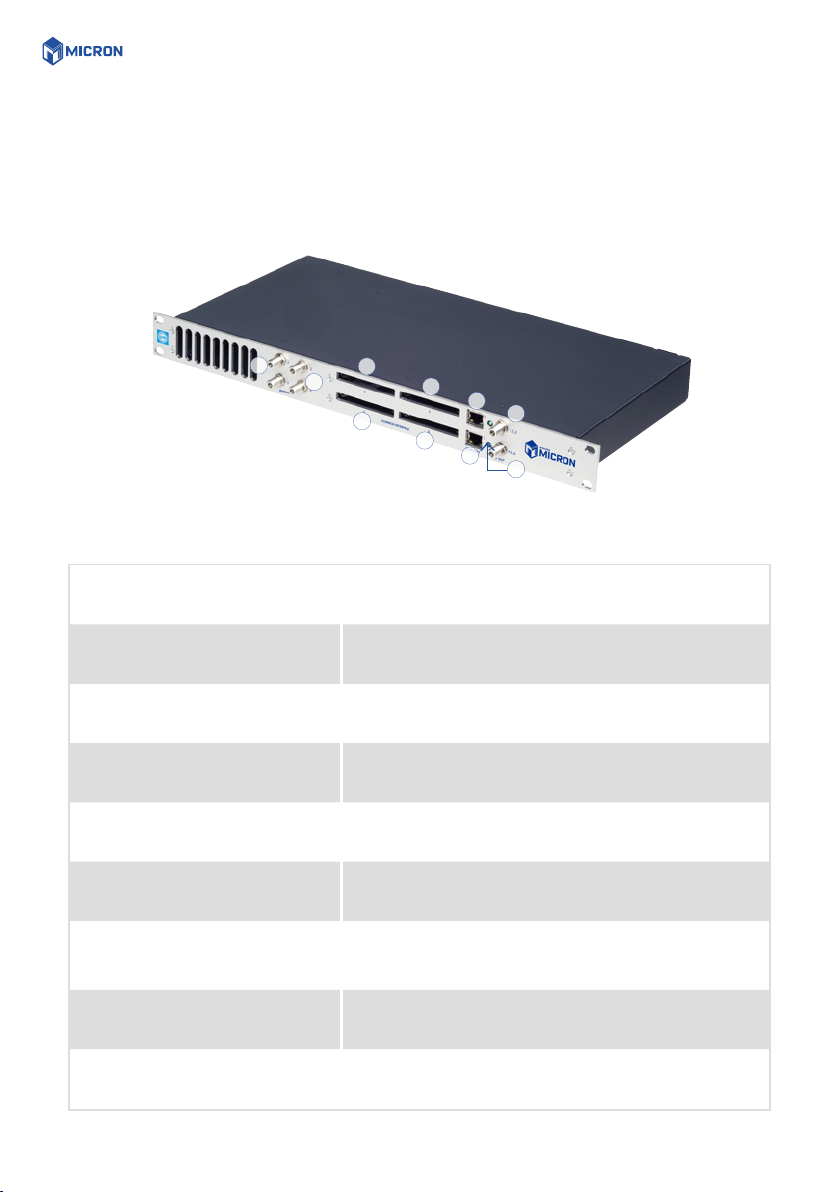
3. CONNECTIONS AND INDICATIONS
1
2
3
5
4
7
8
9
10
6
1. Antenna inputs 1:1 and 2:1 Connect the satellite/terrestrial/cable signal for Ch1 and Ch2
or for all three output channels here.
2. Antenna input 1:2 and 2:2 Connect the satellite/terrestrial signal for Ch3 here (Source
duplication mode OFF).
3. Common Interface 1:1 Insert a Common Interface module into this slot (Supports
decryption for Channel 1 and 2)
4. Common Interface 1:2 Insert a Common Interface module into this slot (Supports
decryption for Channel 3)
5. Common Interface 2:1 Insert a Common Interface module into this slot (Supports
decryption for Channel 4 and 5)
6. Common Interface 2:2 Insert a Common Interface module into this slot (Supports
decryption for Channel 6)
7. Ethernet port 1:1
8. Ethernet port 2:1
RJ-45 port for 10/100 baseT Ethernet. Connect your PC to
these ports for management, IP input and upgrades.
9. RF-output(s) 1:1-3 and 2:4-6 Combined 3 channel RF outputs for connection to your
SMATV network
10. Indicator LED(s) Status indicator

IP SETTINGS 6
4. IP SETTINGS
The MyM Pro MICRON has an embedded web server
allowing a web browser to connect to the unit for settings
and management.
No controller software is needed, The MyM Pro MICRON
has by default static IP address(es) for connecting your PC
to the unit.
The MyM Pro MICRON is delivered with the default IP
address: 192.168.0.20 for port 1 and 192.168.0.21 for
port 2 in a MICRON 6.
First time installation requires that you set a static IP
address on your computer. For example set your PC to IP
address: 192.168.0.19 and Net mask: 255.255.255.0.
4.1 TCP/IP SETTINGS FOR WINDOWS XP
Select ”Start”, ”Control panel” and ”Network
connections”. Next select “Network and Internet
settings”. ”Right click” on [Settings for local network] and
select [Properties].
In Local Area Connection Properties select [Internet
protocol (TCP/IP)] and [Properties].
Select [Use this IP address] and write: 192.168.0.19 and
select [Net mask] 255.255.255.0. Click [OK] and then
click [Close].
For PC with other Operating Systems (OS) than
Windows, please consult the Owners manual
for your PC for [IP/Network settings].
IP SETTINGS 7
4.2 CONNECTING YOUR PC TO THE MYM PRO MICRON
Connect the MyM Pro MICRON power cords to a wall outlet. See section 6 for installation.
Next connect your PC to the MyM Pro MICRON with a network cable.
Start your web browser and write the IP address 192.168.0.20 and 192.168.0.21 for second port*in the
address field of your browser.
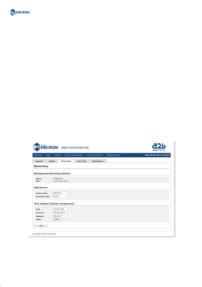
4.3 SETTINGS OF IP ADDRESS
Click the [System options] menu and then press [Networking] to set a new IP address, Netmask and
Gateway for the MyM Pro MICRON. Also DNS servers can be chosen.
IGMP setting shall be in accordance to that version that is used in the network (IP in).
Click [SAVE] after settings are done.
*) MyM Pro MICRON 6
MENUES AND SETTINGS 8
5. MENUES AND SETTINGS
All necessary settings can be made in the web GUI via a web browser. When first connection is made
with the MyM Pro MICRON following overview menu will appear.
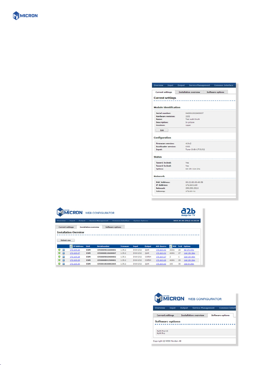
5.1 OVERVIEW MENU
CURRENT SETTINGS
Contains information of current input and output signals,
if the tuners are locked to a signal, firmware version,
bootloader version, hardware revision, serial number and
current IP Network settings. A Name and Description can
be written by click on the Edit button.
INSTALLATION OVERVIEW
In this menu you can see all MyM Pro MICRON units when
connected to a switch and also see EXM/OXM units that
are connected to the same switch.
SOFTWARE OPTIONS
In this menu you can see which software options that are
activated.
To continue with settings click the [Input] name in the
banner.
MENUES AND SETTINGS 9
5.2 INPUT SETTINGS
As the MyM Pro MICRON contains ”multituner” start by
selecting either DVB-T/T2, DVB-S/S2, DVB-C or IP input.
After that you choose [Tuner 1] or/and [Tuner 2] for
settings of the tuner parameters also depending on choice
of [Source duplication] that can be either OFF or ON with
both CI used or ON with only one CI chosen for both Ch1,
Ch2 and Ch3 out.
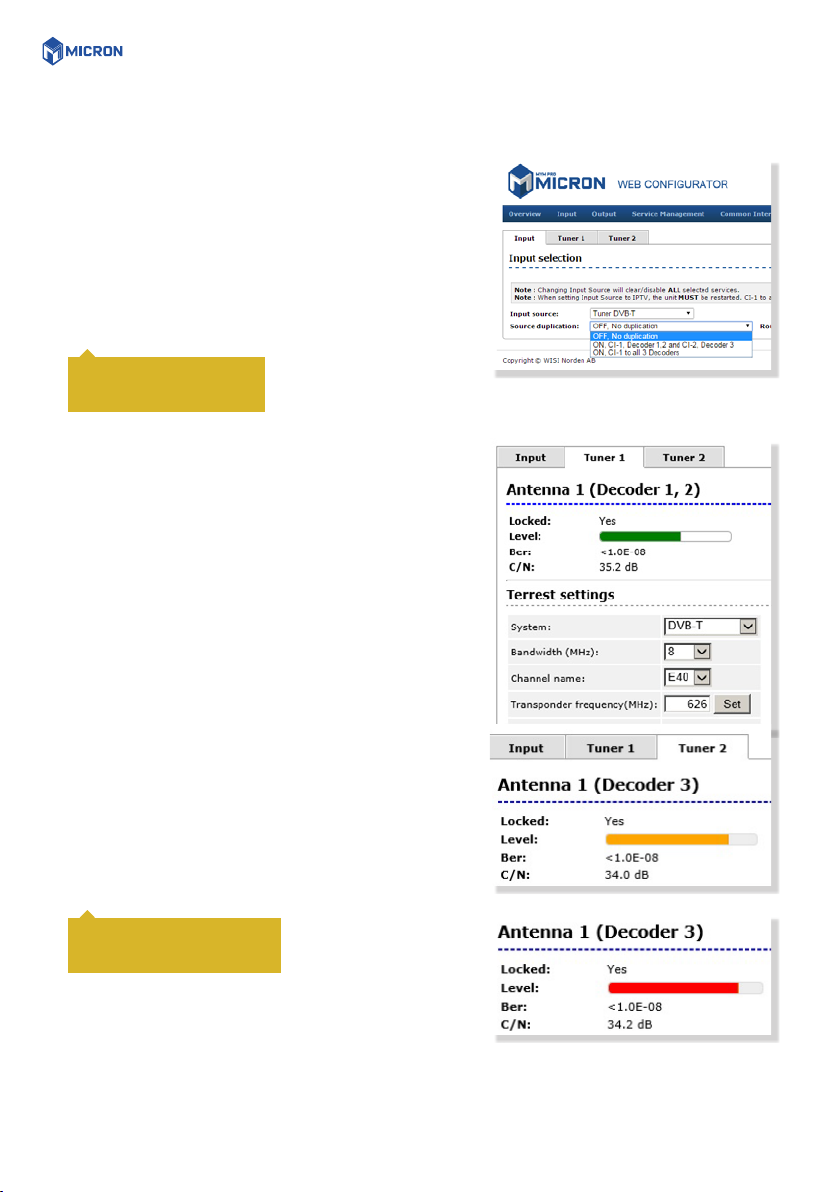
5.2.1 DVB-T/T2 RECEPTION
For receiving from terrestrial, start with chosing Tuner
DVB-T/T2 as [Input source]. Tuner 1 provides the service list
for RF output Ch1 and Ch2. Tuner 2 provides the service
list for RF output Ch3. The tuner can also be ”Disabled”.
[Bandwidth] can be selected between 6, 7 or 8 MHz.
Select input channel from [Channel name] scroll list or
write the center frequency of the wanted Mux and press
[Set]. You can see if Tuner is locked. [Level] shall show a
green bar to be correct. If the bar is Orange or Red the
input level is out of recommended window (too low or too
high).
If you have an MyM Pro MICRON 6 proceed with next two
tuners [Tuner 3] and [Tuner 4] after moving the TP cable to
the other RJ 45 port (if not using switch). Tuner 3 provides
the service list for RF output Ch4 and Ch5. Tuner 4
provides the service list for RF output Ch6.
With source duplication
ON, only Tuner 1 is in use.
Do not press [Set] if channel
is chosen from the scroll list
CLOSE TO LIMIT
OVER LIMIT
MENUES AND SETTINGS 10
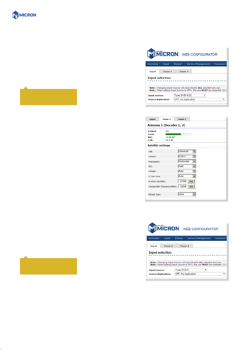
5.2.2 DVB-S/S2 RECEPTION
For receiving from satellite, start with chosing Tuner
DVB-S/S2 as [Input source].Tuner 1 provides the service list
for RF output Ch1 and Ch2. Tuner 2 provides the service
list for RF output Ch3 when Source duplication is chosen
as OFF.
Select the actual Input parameters for the satellite
transponder you receive.After the tuner has locked you
can read the values for [Locked], [Level] and [C/N].
[Level] shall show a green bar to be correct. If the bar
is Orange or Red the input level is out of recommended
window (too low or too high).
If you have an MyM Pro MICRON 6 proceed with next two
tuners [Tuner 3] and [Tuner 4] after moving the TP cable to
the other RJ 45 port (if not using switch). Tuner 3 provides
the service list for RF output 4 and 5. Tuner 4 provides the
service list for RF output 6.
5.2.3 DVB-C RECEPTION
For receiving from cable, start with choosing Tuner DVB-C
as [Input source].Tuner 1 provides the service list for RF
output Ch1 and Ch2. Tuner 2 provides the service list for
RF output Ch3 when Source duplication is chosen as OFF.
With source duplication
ON, only Tuner 1 is in use.
With source duplication
ON, only Tuner 1 is in use.
Tabla de contenidos


