WILMS KT 320 Manual de usuario

Introduction
Overview
Serial number: This manual covers Wilms Dehumidifiers with
serial numbers from:
606230852405
Warning: It is the responsibility of the operator to read and understand this service manual
and to use the correct operating procedures.
Read the entire manual before the initial start-up of the dehumidifier. It is important to
know the correct operating procedure for the unit and all safety precautions to prevent
the possibility of property damage and/or personal injury.
Contents: This service manual covers the following main topics:
Topic: Page
General information 2
Product-and functional description 3 - 4
Set up and transport of the unit 5 - 6
Manual 7
Service guide 8
Preventive maintenance 9 - 10
Accessories 11
Fault finding and solving 12
Service agreement 13
Technical information 14
Measurements 15
Wiring diagram 16
Cooling circuit 17
Spare parts 18 - 23
1

General Information
Introduction: This section gives the general information about this service manual and
about the unit.
Target Group: The target group for this service manual is the technicians who install, maintain, and
exchange parts on the units.
Copyright: Copying of this service manual, or part of it, is forbidden without prior written
permission from Hans Wilms GmbH & Co. KG - Erftstrasse 34 - 41238 Mönchengladbach.
Reservations: Hans Wilms GmbH & Co. KG reserves the right to make changes and alterations to the
product and the service manual at any time without prior notice or obligation.
EU-Conformity
Declaration: Hans Wilms GmbH & Co. KG - Erftstrasse 34 - 41238 Mönchengladbach - hereby declares that
the units mentioned below:
Dehumidifier, Type KT 320, KT 420, KT 820,
covered by this declaration, is in conformity with the following directives:
98/37/EG Directive on the Safety of Machines
73/23/EWG Low Voltage Directive
89/336/EWG EMC Directive
97/23/EWG The Pressure Equipment Directive
2002/95/EG RoHs Directive
(Restriction of use of certain dangerous material in
electro-devices).
2002/96/EG RoHs-Directive for electro devices
- and is manufactured in conformity with the following standards:
EN ISO 12100 Safety of machines
EN 60 335-2-40 Safety of Dehumidifiers
EN 61 000 EMV
Moenchengladbach, May 6,2008 Jochen Wilms
Place - Date Signature Managing Director
Recycling: The unit is designed to last for many years. When the time comes for the unit to be
recycled, the unit should be recycled according to national rules and procedures to
protect the environment.
2

Product- and functional description
Introduction: This section will give you a description of the machines and the functions:
Principles of The following describes the air flow
operation: through the dehumidifier:
The air flow through the
dehumidifier.
A
fan draws in humid air through a
filter to the dehumidifier.
The air is cooled down and humidity/water
drops are led down to the water
tank.
The air is re-heated by e.g. the operation
of the dehumidifier (approx. increase in
temperature is +5°C/41°F).
Due to the repeated air circulation through the dehumidifiers, the air humidity is
continuously reduced whereby achieving rapid, but gentle drying.
The dehumidifier will operate continuously unless a hygrostat (accessories - page 11)
is connected.
Illustration: This illustration gives an overview of the dehumidifier:
Handle Operator Control
Power Cable
Air Outlet
Supply air inlet with
PPI filter behind the grill
Water Tank
Wheels
Front View Rear View
Water Tank: Water is collected in the water tank. Alternatively, you can also setup the dehumidifier for
permanent drainage with the adapter for hose connection (accessories).
When the water tank is full, the dehumidifiers shut off automatically.
Emptying of the water tank, see manual, page 7.
Operation of the unit is not possible once the water tank is removed.
3
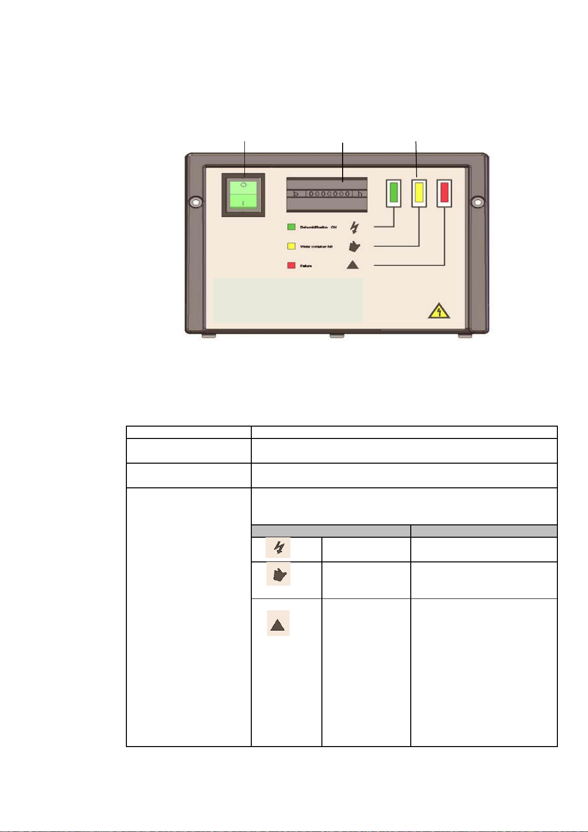
Control Main Switch Hour Meter Display
Fig. 4
Function
Main Switch Switching-on/-off power
Hour Meter Trip counter, reading the number of operating hours
Display Icons and meaning of the icons:
Icon ON/OFF Power is on
full because water tank is full.
cooling circuit.
has occurred.
Product- and functional description
Illustration, This illustrates the operator control:
Display/Operator
Part
/
The following describes the function of the different parts of the operator control:
Part Function
Illuminates when ….
Water tank The units are out of operation
Too high The dehumidifiers are automa-
pressure/tempe- tically put out of operation due
rature in the to a temperature over 60°C/
140°F to protect the compres-
sor.
The dehumidifiers will automati-
cally operate again after 30 min.
The red lamp illustrates during
the 30 min. to indicate an error
4

Set up and transport of the unit
Introduction: This section provides information required for:
unwrapping the unit
making it ready for use
transportation of the unit
Warning: upright position for at least one hour before put into service!!!
Procedure: Follow these steps to unwrap the unit and make it ready for use:
1on the top.
2
3
lying down.
4
screws.
Placing: Place the dehumidifier:
to ensure good air circulation.
front.
distance on the outlet air side should be 3 m.
• Away from any source of heat e.g. a radiator.
dehumidified.
If the dehumidifier has been laid down during transport, it is imperative to place it in
Step Action Illustration
Open the cardboard box
Place the box with the hand-
le and wheels on the
floor.
Pull the handle and wheel
of the dehumidifier out while
Loosen the finger screws
and pull the handle up and
tighten the finger
• In the middle of a room - if possible -
• Where air can be sucked in freely at the
back of the unit and blown out at the
• With a minimum distance on the supply air
side from a wall of about 60 cm. The minimum
In addition, ensure that windows and doors to the open are closed in the room to be
5

Set up and transport of the unit
Connection: 230/50 Hz socket. Protect the socket with a 10 A fuse or a 16 A circuit breaker.
Wheels: the cabinet on the steps.
dehumidifier:
Lift with one person at each arrow. Lift by lifting strap.
Stacking: stacked on top of each other.
only - as illustrated.
dehumidifier.
Electrical The dehumidifier is complete with cable and plug and ready for connection to a
The wheels are mounted opposite the cabinet for easy transport up stairs without damaging
Transport/- Two people or a crane can move the dehumidifier, see instruction below:
Replacing of the Note: Observe local working environment rules regarding heavy lifting.
2 People Hoist/Crane
Max. 2 dehumidifiers should be
Stacking of 2 dehumidifiers
Press the handle of the lower
dehumidifier to the bottom be-
fore stacking. The handle then
fits into a notch on the upper
6

Manual
Starting: Please follow this procedure to start up/shut down the dehumidifier:
Stop Action Illustration
Start up
switch on
Switch off main switch is off. Main Switch
water tank: difier shuts down automatically when the water tank is removed.
Follow the procedure to empty the water tank.
1
difier.
2clear off the dehumidifier.
3through the side opening.
4 Put the tank back in place.
positioned.
and the fan and compressor
start up. The light of the
main switch is on.
Set the main
and the fan and compressor
Shut down/ shut down. The light of the
Emptying the It is not necessary to shut down the dehumidifier when emptying the water tank. The dehumi-
Step Action Illustration
Pull the handle in front of the water tank to
remove the tank halfway out of the dehumi-
Grab the side handles of the tank and lift
Tilt the tank sideways to pour the water out
Important!!!
Check that the water tank is correctly
7
Service Guide
Overview:
Note: Spare parts - from page 18
Important: Always disconnect the power cable from the unit before doing any service!
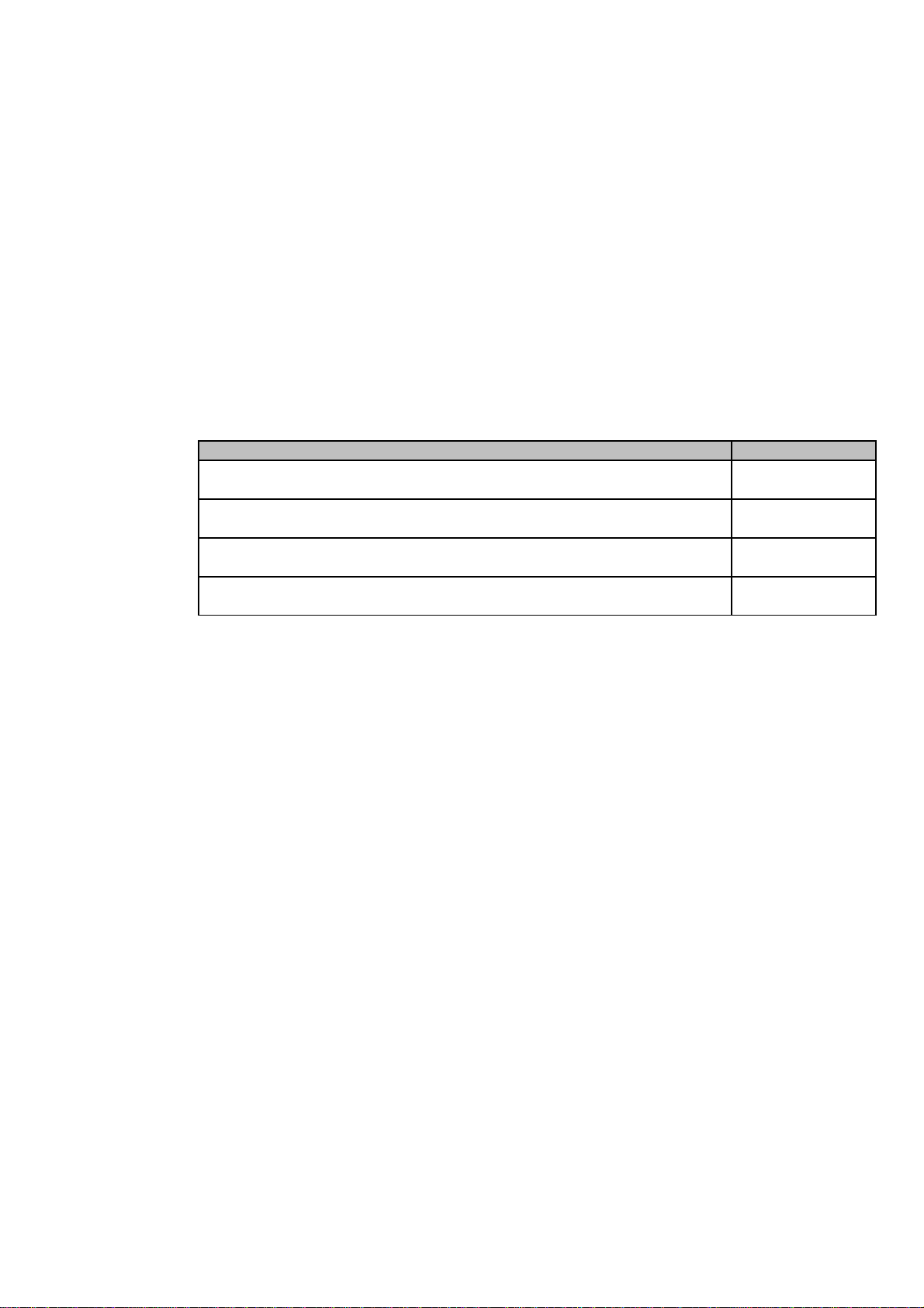
Content: This chapter covers the following topics:
Topic See page
Preventive maintenance 9 - 10
Accessories 11
Fault finding and solving 12
Service agreement 13
8

Preventive Maintenance
Introduction: This section contains description of the recommended monthly and annual maintenance.
Service: and/or corrective maintenance - see section "Service-Agreement" - page 13.
Important! maintenance.
Inspection:
1outwards.
2
is only a little dirty.
Change the filter if it is very dirty.
3 Clean the water tank.
4the cover outwards about 30°.
Proper maintenance of the unit is necessary in order to achieve trouble-free operation.
Contractual Hans Wilms GmbH & Co. KG provides contractual service agreements covering preventive
Always disconnect the power cable from the unit before doing any preventive
Monthly Please follow this procedure to carry out the monthly preventive maintenance:
Step Action Illustration
Open the front grill by tilting it
Remove the filter, either rinse it with lukewarm
soapy water or vacuum-clean it if the filter
Remove the two screws in each side and tilt
9

Preventive Maintenance
Inspection 5dehumidifier.
6soft brush and vacuum-clean/compressed air.
Mount the cover and put the water tank back
Note:
Check that the water tank is fitted
correctly.
Annual
Step
2 Vacuum-clean the unit, be very thorough with the condenser and the
3
• Fan blades
4 Carefully clean the unit (be extra careful around the fins) with water,
8 Check that the hour meter is running, see "Product and functional description
page 3 - 4.
Action
Monthly Step Action Illustration
Lift the cover and clear of the
Clean the evaporator coil by brushing with a
in place.
Follow the procedure to carry out the annual preventive maintenance.
Inspection:
1 Carry out the monthly maintenance as described above.
evaporator.
If the unit is very dirty, move on to step 3 and 4 - otherwise move on to
step 5.
Spray water based soap on the:
• Evaporator-/condensor coil
using a household spray or similar item.
however, not directly on electrical components.
5 Check the fan.
6 Mount front-and rear cover and water tank.
7 Check and tighten all cover plate screws when necessary.
10
Este manual sirve para los siguientes modelos
5
Tabla de contenidos
Otros manuales de Deshumidificador de WILMS


