Whirlwind 400A Series Manual de usuario

Manufacturer of Composite Constant Speed Propellers
WHIRLWIND
Owner’s Manual
400A Series
(Rev 2018-1)
WHIRL WIND AVIATION
1419 STATE ROUTE 45 SOUTH
PO BOX 190
AUSTINBURG, OH 44010 U.S.A.
PHONE: 440-275-1540
FAX: 440-275-3192
http://www.whirlwindaviation.com
Email: [email protected]
A V I A T I O N

Model:
400A
Serial Number:
400A-
Manufacture Date:
Blade Color:
PPG No:
Tip Color:
PPG No:

Section 1: Introduction................................................1-1
Section 2: Overview.....................................................2-1
2.1 Description .................................................................2-1
2.2 Construction...............................................................2-2
Section 3: Propeller Identification........................3-1
Section 4: Instructions for Installation................4-1
4.1 Propeller and Spinner Installation..............................4-1
4.2 Spinner Dome Installation..........................................4-4
4.3 Governor Installation..................................................4-5
Section 5: Propeller System Operation............5-1
5.1 First Run-Up...............................................................5-1
5.2 Inspection After First Run-Up.....................................5-2
5.3 Dynamic Balance of the Propeller..............................5-3
5.4 Inspection After First 2 Hours of Flight......................5-3
5.5 Overspeed Warning...................................................5-4
5.6 RPM Recommendation..............................................5-4
Section 6: Propeller System Inspection...........6-1
6.1 Preflight Check...........................................................6-1
6.2 50 Hours Inspection...................................................6-2

Section 7: Propeller System Maintenance.....7-1
7.1 Teardown Inspection Schedule.................................7-1
7.2 Use of Propeller Log Book.........................................7-1
Section 8: Propeller Log Book...............................8-1
8.1 Maintenance & History ..............................................8-1
8.2 Transfer of Ownership...............................................8-7

Congratulations on your propeller purchase from
Whirl WindAviation!
To ensure many hours of trouble free operation of your new Whirl
Wind propeller please read and follow the operation and
maintenance recommendations in this manual.
The Whirl Wind 400A Series propeller is a composite constant speed
hydraulically controlled propeller. This fully constant speed propeller
will automatically adjust blade pitch angle to maintain the selected
engine RPM setting. A single acting piston (inside the hub) powered
by engine oil changes the blade pitch. Oil pressure is adjusted and
regulated by the engine driven governor. Once an engine RPM is
selected, it will be held constant at all flight airspeeds and power
settings by the governor automatically.
The propeller control lever is used to set the desired engine RPM.
Once the engine RPM is set, it is held constant by the governor,
which maintains this preset RPM by varying the propeller oil
pressure automatically. Mechanical stops for high and low pitch limit
the pitch change travel of the propeller.
Whirl Wind propellers are experimental class and are not subject to any
Federal Aviation Administration regulations. The operator acknowledges that
these are experimental propellers and agrees to assume all risk in operating
them on an experimental aircraft or any other machine. Any and all
information in the owner’s manual, service letters and other documentation
are suggestions only and may not apply to an operator’s specific application.
1-1
Section
1
Section 1: Introduction

2.1 Description
The 400A Series propeller has been designed to maximize
the performance of your airplane! This propeller delivers
exceptional performance for the modern day utility aircraft.
The exceptional performance is derived from advanced
aerodynamic engineering techniques including computerized
airfoil modeling.
Whirl Wind has made significant developments in the
construction of the carbon composite propeller blades
ensuring a strong, light and durable propeller system. The
blade twist has been optimized for maximum performance
and the wide chord allows for more low-speed thrust and
braking.
.
The 400A Series is a three-blade hydraulically controlled
constant speed propeller system designed for aircraft using
a Lycoming IO-540 or equivalent engine.
2-1
Section
2
Section 2: Overview

2.2 Construction
The 400A Series propeller blades are constructed from
advanced thermoset composite materials. Each blade is
equipped with a nickel leading edge erosion shield to protect
the blade leading edge from debris damage. The 400A
Series System includes: propeller, spinner, and all hardware
needed for installation.
The 400A Series hub is CNC machined from certified
aerospace aluminum alloy, which is then shot peened and
anodized. The hub blade sockets are equipped with ball
bearings to ensure smooth pitch change of the blades
throughout the life of the propeller system. This propeller can
be flown in rain and off unimproved airstrips.
2-2

Each Whirl Wind propeller system has a factory designated model
number and serial number, which will identify the hub and propeller
serial number. The propeller system blades will have individual
serial numbers etched on the ferrule of each blade near the root end.
All Serial numbers can be found on the owner’s data sheet.
Example: 200G-CS-108
Series and Hub Style
200G-CS
Propeller Serial Number
108
Blade Serial Numbers
112, 113
3-1
Section
3
Section 3: Propeller Identification

4.1 Propeller and Spinner Installation
WARNING! DO NOT OPERATE THE ENGINE /
PROPELLER WITH ONLY THE SPINNER FILL-
IN PIECES INSTALLED!
IF THE ENGINE AND PROPELLER ARE TO BE RUN
WITHOUT THE SPINNER DOME INSTALLED IT IS
IMPARATIVE THAT THE FILL-IN PIECES ALSO BE
REMOVED. The centrifugal force will damage or destroy the
fill-in pieces without the support of the spinner dome. (The
engine and propeller can be operated with only the spinner
rear bulkhead installed.)
* For safety reasons always turn the propeller opposite
of the usual direction of rotation.
4-1
Section
4
Section 4: Instructions For Installation
The Whirl Wind 400A Series propeller comes equipped with
a composite spinner and rear bulkhead.
Step 1: Before beginning installation of the 400A Series
propeller system inspect the O-Ring located in the propeller
hub flange and make sure the O-Ring is in good condition.
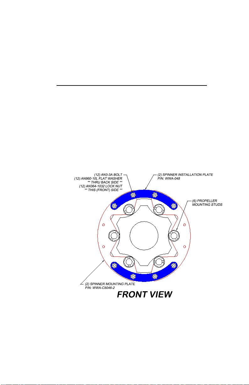
For Two Piece Rear Spinner Bulkhead Installation:
Step 2: Using the supplied AN3 bolts and nuts, install the (2)
temporary spinner installation plates as detailed below. The
installation plates are provided to maintain the proper
spacing of the (2) spinner mounting plates when the
propeller mounting studs are tightened.
4-2
Tabla de contenidos


