
Westover FBP Series Manual de usuario

FBP Probe Microscope
User Manual
18421 Bothell-Everett Hwy.
Suite 110
Mill Creek, WA 98012
Phone: (800) 304-3202 or (425) 398-1298
Fax: (425) 398-0717
E-mail: info@westoverscientic.com
Web: www.westoverber.com
with HD1 Display
ZP-PKG-0316
REV 2

CERTIFICATION
Tested Equipment
All pre-qualication tests were performed internally at Westover Scientic, Inc., while all nal tests were
performed externally at an independent, accredited laboratory. This external testing guarantees the
unerring objectivity and authoritative compliance of all test results. Westover Scientic’s Commerce and
Government Entities (CAGE) code under the North Atlantic Treaty Organization (NATO) is 0L8C3.
FCC Information
Electronic test equipment is exempt from Part 15 compliance (FCC) in the United States.
European Union
Electronic test equipment is subject to the EMC Directive in the European Union. The EN61326
standard prescribes both emission and immunity requirements for laboratory, measurement, and control
equipment. This unit has been tested and found to comply with the limits for a Class A digital device.
Independent Laboratory Testing
This unit has undergone extensive testing according to the European Union Directive and Standards.
© 2007 Westover Scientific, Inc. All rights reserved.

INTRODUCTION................................................................................................................................................................................2–3
Key Terms & Concepts ....................................................................................................................................................................................2
Fiber Connectors .................................................................................................................................................................................3
Simplex, Ribbon & Jewel Fiber Connectors........................................................................................................................3
Dirt & Contamination........................................................................................................................................................................3
Scratches...................................................................................................................................................................................................3
FBP PROBE MICROSCOPE.........................................................................................................................................................4–5
Overview .............................................................................................................................................................................................................4
Specication & Models ....................................................................................................................................................................4
Installation...............................................................................................................................................................................................................5
Connecting the Probe to the HD1 Display..........................................................................................................................5
Controls......................................................................................................................................................................................................................5
Focus Control ....................................................................................................................................................................................5
Magnication Control .....................................................................................................................................................................5
FBPT PROBE TIPS ..............................................................................................................................................................................6–7
Overview ...................................................................................................................................................................................................................6
Barrel Assemblies ................................................................................................................................................................................6
FBPT Tip Categories ...........................................................................................................................................................................6
Tip Assembly ..........................................................................................................................................................................................................7
HD1 DISPLAY.....................................................................................................................................................................................8–11
Overview ...................................................................................................................................................................................................................8
Installation...............................................................................................................................................................................................................9
Battery Installation .............................................................................................................................................................................9
Connecting the Probe Microscope ..........................................................................................................................................9
Controls...................................................................................................................................................................................................................10
Auto Shut-down Intervals (shared function with Contrast Control).......................................................................10
Contrast Control (shared function wth Auto Shut-down Interval)............................................................................10
Hanging / Standing Accessory ................................................................................................................................................11
Removable Magnet (optional)...................................................................................................................................................11
CONTENTS

INTRODUCTION
Inspection of ber optic interconnects is essential for the optimal performance and longevity of ber optic connectivity.
Throughout their lives, ber connectors must be inspected, analyzed and cleaned to maintain an acceptable level of functionality.
By developing and introducing the equipment and software to inspect, analyze and clean ber connectors, Westover Scientic is
able to provide a comprehensive solution for the performance and preservation of ber optic interconnects.
Key Terms & Concepts
Fiber Connectors
Fiber connectors enable ber-to-ber mating by aligning the
two optical bers. Fiber connectors come in various types and
have dierent characteristics for use in dierent applications.
The main components of a ber connector are detailed below:
Body
Houses the ferrule that secures the ber in place; utilizes a
latch and key mechanism that aligns the ber and prevents
the rotation of ferrules of two mated connectors
Ferrule
Thin cylinder where the ber is mounted and acts as the
ber alignment mechanism; the end of the ber is located
at the end of the ferrule
Fiber
Cladding
Glass layer surrounding the core, which prevents the
signal in the core from escaping
Core
The critical center layer of the ber; the conduit that
light passes through
-
-
Fiber Connector (Simplex)
Ferrule
Body
Optical Fiber
Fiber
Body
Ferrule
INTRODUCTION Westover Scientific
Key Terms & Concepts FBP Probe & HD1 Display
2
Simplex Fiber Ribbon Fiber
Core
Cladding
Ferrule

Simplex, Ribbon & Jewel Fiber Connectors
Dirt & Contamination
Simplex Fiber Connector
A simplex ber connector contains a single ber located in the center of the
ferrule. Common types include SC, LC, FC and ST.
INTRODUCTION
Simplex, Ribbon & Jewel Fiber Connectors, Dirt & Contamination, Scratches
Ribbon Fiber Connector
A ribbon ber connector contains multiple linear bers (4, 8, 12, 24, 48 or
72) in a single connector to provide high-density connectivity. The most
common conguration is MPO (also called the MTP®).
Multiple Fibers
Ribbon Fiber Connector
Ferrule Fiber
Simplex Fiber Connector
If dirt particles get on the core surface the light becomes blocked, creating unacceptable insertion loss and back-reection.
Furthermore, those particles can permanently damage the glass interface, digging into the glass and leaving pits that create
further back-reection if mated. Also, large particles of dirt on the cladding layer and/or the ferrule can introduce a barrier that
prevents physical contact and creates an air gap between the bers. To further complicate matters, loose particles have a tendency
to migrate.
Scratches
Scratches are typically created during polishing, cleaning or mishandling ber connectors. Scratches that touch the core are
problematic because they create back reection.
Clean Fiber Dirt Contamination Pit/Chip Contamination Scratch
Jewel Fiber Connector
A jewel ber connector is a simplex ber with a polyimide coating/layer
around the cladding and is designed for exceptional environments such as
military, oil & gas, avionic and/or high-temperature settings.
3
Light Transmitted
Clean
Connection
Core
Cladding
Clean Connection
Core
Cladding
Back Reflection
Light Transmitted Insertion Loss
Dirt
Back Reflection
Light Transmitted Insertion Loss
Pit
(permanent damage)
Core
Cladding
Dirt Reection Pit Reection
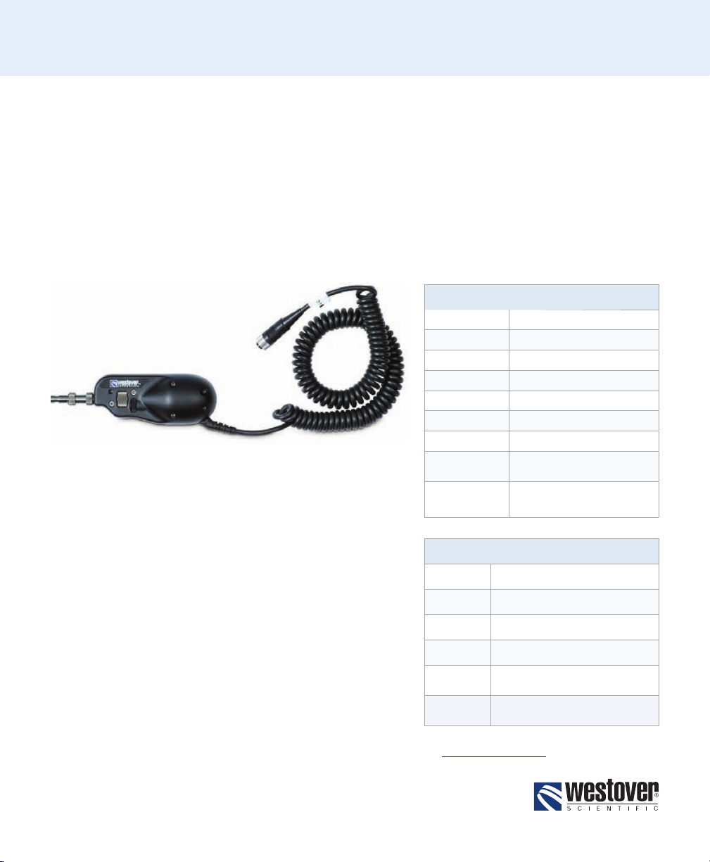
Overview
Westover’s FBP Series Probe is a portable video microscope used to inspect ber optic connectivity. While most ber
microscopes are limited to inspecting “male”connectors (e.g., patch cords, pigtails, etc.), the FBP Probe is designed to inspect male
connectors,“female”connectors (e.g., bulkhead) and optical devices, such as transceivers. The probe is specially designed to t and
operate comfortably and easily in-hand, allowing the user to inspect hard-to-reach connectors that are installed on the backside of
patch panels or inside hardware devices. This eliminates the need to access the backside of patch panels or disassemble hardware
devices prior to inspection.
FBP PROBE MICROSCOPE
Probe Specications
Dimensions 14.0 cm x 4.6 cm x 4.4 cm
Weight 180 g
Cord Length 240 cm
Connector 4- or 6-pin Hirose™ male
Camera Type 1/3” CMOS Sensor
Video Output NTSC or PAL
Light Source Blue LED, 100,000+ hour life
Lighting
Technique Coaxial
Power Source From HD1, HD2 or HD3 Display
or USB port of PC
Common Probe Models*
FBP-P1 Analog, Single (Low) Mag., NTSC
FBP-P2 Analog, Single (Low) Mag., PAL
FBP-P5 Analog, Dual (Low & High) Mag.,
NTSC
FBP-P6 Analog, Dual (Low & High) Mag.,
PAL
FBP-P505 Analog, QuickCapture™, Dual Mag.,
NTSC
FBP-P605 Analog, QuickCapture™, Dual Mag.,
PAL
Connect with Westover’s portable hand-held display devices
(HD1, HD2 and HD3 Displays)
Connect to USB Image Capture Module (digital converter) for use
with PC
Connect to Video Output Module (external bench-top display)
•
•
•
Analog Probes
Used with USB Image Capture Module
Instantly capture ber end-face image on PC screen with built-in
video capture button
Inspect and capture image with one hand
•
•
•
QuickCapture™ Analog Probes
* Additional models available.
See www.westoverber.com for details.
FBP PROBE MICROSCOPE Westover Scientific
Overview & Specifications FBP Probe & HD1 Display
4

FBP PROBE MICROSCOPE
Installation & Controls
Installation
Connecting the Probe to the HD1 Display
Locate the 4-pin “female” end on the display.
Align the notch-keys of the probe’s coil cord end (“male”) then
insert into the “female “ end of the display and screw in to tighten
and secure.
1.
2.
Step 2Step 1
The Focus Control on the probe allows the user to adjust focus manually of the live ber end-face image on the display.
Focus Control
Magnication Control
The Magnication Control (available only on Dual Magnification Probes) allows the user to switch between Low and High
magnications of the ber end-face image.
The basic design of the FBP Series Probe Microscope incorporates an imaging system, integrated light source, video camera,
focus mechanism and magnication control. The probe is fully assembled and is powered by the HD1 Display. The only assembly
required by the user is the connection to the display unit and installation of the appropriate barrel and/or the inspection tip. The
FBP-P5 analog probe is also equipped with a 4-pin circular Hirose™ connector with notch-keys which allows for a secure and rm
latch-lock connection to the HD1 Display.
Controls
5
Focus Control
adjust focus on the display screen
Magnication Control*
switch between low & high
magnification (200X/400X)
Barrel Assembly
FBP-P5
4-pin Connector
connects to the HD1 Display

FBPT PROBE TIPS Westover Scientific
Overview, Barrel Assemblies, FBPT Tip Categories FBP Probe & HD1 Display
6
Overview
FBP Probe Microscopes use a variety of tips and barrel assemblies for inspection. These connector-specic and universal
inspection tips are interchangeable, which allow the probe to interface with dierent types of ber connectors. A wide range of
unique tips is available at Westover and is currently being applied in numerous industry-specic settings (e.g., component/system
manufacturers, network service providers, premise networks, military & aerospace). Below are examples of barrel assemblies and
inspection tips available at Westover.
FBPT PROBE TIPS
Barrel Assemblies
The barrel assembly houses the objective lens and works in conjunction with a
number of tips.
NOTE: Certain tips are equipped with optics and do not need a barrel assembly
(e.g., Long Reach Tips [FBPT-LC-L], Angled Tips [FBPT-SC-A6]).
FBPP-BAP1
FBPP-BAP2
FBPP-BAP3
FBPT-SC (Bulkhead)
FBPT-U25M (Patch Cord)
Standard Tips (Bulkhead & Patch Cord)
Standard bulkhead tips allow the user to inspect the ber end-face on the“female”side
of the bulkhead (e.g., inside hardware devices or on the back side of patch panels).
Standard patch cord tips allow inspection of “male” ends of a ber connection (e.g.,
patch cords, pigtails, etc.). “Universal” tips include the FBPT-U25M, compatible with
2.5mm ferrules (e.g., FC, SC, ST) and the FBPT-U12M, used to inspect 1.25mm ferrules
(e.g., LC, MU).
FBPT Tip Categories
FBPT-LC-L
Long Reach Tips
Long reach tips have a 1/2” longer reach than standard tips, and allow the user to
inspect the ber end-faces in tight, hard-to-reach spaces.
FBPT-SC-APC
APC Tips
APC tips are designed with an angle that complements
the end-face of an APC polish ber connector. This
allows the entire ber image to stay in focus during
inspection.

FBPT PROBE TIPS
FBPT Tip Categories & Tip Assembly
7
FBPT-MTP
RibbonDrive™ Tips
Westover’s patented RibbonDrive™ tips are specialty tips that allow inspection of high-
density, multiber array connectors that are mounted within a bulkhead adapter. Each
tip mates securely with connectors using a precision-keyed mating adapter interface.
The patented “panning knob” allows the user to view each ber individually in the
linear array.
FBPT-SC-A6
Angled Tips
Angled tips, identied by“A6,”are angled 60° to allow easy maneuvering and inspection
of hard-to-reach locations such as transceivers on a printed circuit board (PCB) or
bulkheads located in tight spaces.
FBPT-A801-2-001-R
Alignment Guides
Alignment guides enable the inspection of various military & aerospace connectors
that use a pin & socket design. In addition to providing an alignment channel for
sockets, these alignment guides work in conjunction with a barrel assembly to prevent
the pins from breaking.
Notch-key &
Key Channel
Inspection Tip (FBPT-LC-L)
Retaining Nut
WITHOUT Barrel Assembly
FMA Adapters
FMA Adapters provide optimized inspection for “male” connector ends and are ideal
for inspecting patch cords with multi-ber ribbon and APC polish connectors. FMA
adapters can be utilized by a probe microscope with a universal are adapter (FBPT-
UFMA).
FMA-U12 FBPT-UFMA
(universal flare
adapter)
Objective Lens
Inspection Tip
(FBPT-U25M)
Barrel Assembly
Front & Back
Retaining Nut
Notch-key &
Key Channel
WITH Barrel Assembly
Tip Assembly

Overview
The HD1 Series Video Display is a durable, lightweight,
ergonomic, drop-tested display unit for use with any NTSC FBP or
FBP3 series probe. It features a 3.5” TFT active matrix LCD screen,
which produces a bright, clear, and crisp, high-contrast image of the
ber end-face. It can be powered by 100–240V AC or a rechargeable
Li-ion battery (the Li-ion battery must be in the display for the unit to
operate). The HD1 Display features contrast adjustment, auto-shuto
function (to preserve battery life) and a hanging accessory (for hands-
free operation). It is designed to t comfortably in the user’s grip for
optimal performance. The display uses a 4-pin Hirose™ connector,
which routes power into the probe and video out of the probe. A
conversion cable is also available for 6-pin QuickCapture™ analog
probes.
HD1 DISPLAY Westover Scientific
Overview & Specifications FBP Probe & HD1 Display
HD1 Display Specications
Dimensions 45.7 mm x 43.2 mm x 140 mm
Weight 400 g
Video Display 3.5” TFT LCD
Video Input NTSC with dedicated connector
for Probe or conversion cable
Power Source
Li-ion Battery (Sony® type NP-
550) or AC Adapter/Charger
(100–240VAC)
Note: The battery must be in the
display for the unit to operate.
Battery Life 2 hours continuous use
Charging Time 2 hours
HD1 DISPLAY
8
Hanging
Accessory
Removable Magnet
(optional)
Rechargeable
Li-ion Battery
Compartment
Door
4-pin Connector to
analog probe
AC Power Input
On/O Control
Battery Power
LED
Auto Shutdown
Interval
AND
Contrast Control
AC Power LED
Battery Status
AND
Auto Shut-down
Interval LED’s
Este manual sirve para los siguientes modelos
6
Tabla de contenidos
Otros manuales de Microscopio de Westover

Manuales populares de Microscopio de otras marcas


VWR
VWR VisiScope 384 Series Manual de usuario

Nikon
Nikon ECLIPSE E200 POL Manual de usuario

Leica
Leica DI C800 Manual

ThermoFisher Scientific
ThermoFisher Scientific Continuµm Manual de usuario

ThermoFisher Scientific
ThermoFisher Scientific Continuµm Manual de usuario

Olympus
Olympus SZ61 Manual de usuario