Western Scale m2000D Manual de usuario

m2000D technical manual
high speed 3 channel digital indicator
Manual Release for V1.03D of software
We are continuously improving the manual and will send out updated versions as
soon as the manual has been finalized. More examples and features will be added.
JUNE 2002

m2000D technical manual
Page I
M2000D WEIGHT INDICATOR TECHNICAL MANUAL
Copyright © 2002 Western Scale. All rights reserved.
Published by:
Western Scale
1670 Kingsway Avenue
Port Coquitlam B.C.
Canada
V3C 3Y9
Information in this technical manual is subject to change without notice due to
correction or enhancement. The information described in this manual is the property of
Western Scale. No part of this manual may be reproduced or transmitted in any form,
without the express written permission of Western Scale.
Western Scale Locations
Western Scale Co. Ltd.
1670 Kingsway Avenue
Port Coquitlam B.C.
Canada
V3C 3Y9
Wescale Inc.
Division of Western Scale
3873 Airport Way
Bellingham, WA.
98227 - 9754
INTERNET ADDRESS: www.westernscale.ca

m2000D technical manual
Page II
qINTRODUCTION TO DLC SCALE ALLOCATION ……….
qGENERAL INSTALLATION GUIDE ………………………..
qSECTIONAL SCALE INSTALLATONS……………………...
qHOPPER SCALE INSTALLATIONS ………………………..
qGENERAL ALLOCATION RELATED COMMANDS……...
qGENERAL CABLE CONNECTION GUIDE…………………
qGENERAL DIAGNOSTICS……………………………………
INTRODUCTION
SECTION SCALE
INSTALLATIONS
GENERAL
DIAGNOSTICS
HOPPER SCALE
INSTALLATIONS
GENERAL DLC
COMMANDS
GENERAL CABLE
CONNECTIONS
GENERAL
INSTALLATION
DIGITAL SCALEALLOCATION
GUIDE

m2000D technical manual
Page III
CONTENTS
M2000D SYSTEM INTRODUCTION.......................................................................................................1
GENERAL OVERVIEW..........................................................................................................................1
MAIN FEATURES ..................................................................................................................................1
M2000D SYSTEM SPECIFICATIONS....................................................................................................2
M2000D DIGITAL SYSTEM DIAGRAM................................................................................................3
TYPES OF SCALE SYSTEMS SUPPORTED..........................................................................................4
DLC CHANNEL ALLOCATION.............................................................................................................4
SCALE SETUP USER INTERFACE........................................................................................................6
GENERAL INSTALLATION GUIDE......................................................................................................9
INTRODUCTION AND OVERVIEW......................................................................................................9
POWER SUPPLY CONNECTION...........................................................................................................9
LOAD CELL CONNECTION................................................................................................................10
SERIAL PORT CONNECTIONS...........................................................................................................10
DLC COMMUNICATIONS CABLE CONNECTIONS..........................................................................10
SYSTEM GROUNDING........................................................................................................................11
SECTIONAL SCALE INSTALLATION GUIDE...................................................................................13
521 Assign a Sectional Scale: calibration command.........................................................................14
SECTIONAL EXAMPLE (1)...............................................................................................................15
SECTIONAL EXAMPLE (2)...............................................................................................................16
HOPPER SCALE INSTALLATION GUIDE..........................................................................................19
520 Assign a Hopper Scale: calibration command.............................................................................20
HOPPER EXAMPLE (1) .....................................................................................................................21
HOPPER EXAMPLE (2) .....................................................................................................................22
GENERAL ALLOCATION RELATED COMMANDS .........................................................................25
500 Clear All Remote DLC scale allocations : calibration command................................................25
501 Clear Scale 1 Allocation: calibration command........................................................................25
502 Clear Scale 2 Allocation: calibration command........................................................................25
503 Clear Scale 3 Allocation: calibration command.........................................................................25
525 DLC Load Cell Masking: calibration command........................................................................26
530 Reset Corner Field adjustment entries: calibration command.....................................................27
531 Corner / Section Manual Span Adjustment: calibration command..............................................28
532 Auto Corner Span Adjustment: calibration command................................................................29
551 DLC communications Error Counter: Calibration command......................................................30
552 DLC Packet Counter: Calibration command..............................................................................30

m2000D technical manual
Page IV
555 DLC Software Upgrade Download: calibration command .........................................................31
556 Obtain DLC BIOS Firmware version information: calibration command ...................................31
557 Obtain DLC BOOT Firmware version information: calibration ................................................31
558 DLC Set AD Range For Active Corner: calibration command...................................................32
592 Restore System Setup From DLC slave: calibration command...................................................33
591 Backup System Setup To a DLC slave: calibration command....................................................34
594 Reload Scale Allocation (field replacements): calibration command..........................................34
600 Scale Status/Diagnostics Information: non-calibration command...............................................36
620 DLC Slave Line Status: non-calibration command ....................................................................37
GENERAL CABLE CONNECTION GUIDE.........................................................................................39
M2000D INDICATOR CONNECTIONS ...............................................................................................39
DLC CONNECTIONS ...........................................................................................................................40
SINGLE DLC SLAVE CONNECTION..................................................................................................41
DUAL DLC SLAVE CONNECTION – TYPE 1.....................................................................................42
DUAL DLC SLAVE CONNECTION – TYPE 2.....................................................................................43
GENERAL DIAGNOSTICS....................................................................................................................44
DLC STATUS INDICATORS................................................................................................................44
ERROR MESSAGES.............................................................................................................................47

m2000D technical manual
Page 1
M2000D SYSTEM INTRODUCTION
GENERAL OVERVIEW
A M2000D weighing system consists of an indicator connected remotelly to one or two
DLC remote digital intelligent load cell terminal boxes, supporting up to 16 load cells.
A digital M2000D scale system provides for a high level of data integrity between the
scale platform and indicator for up to a 1000 feet apart. Because the analog scale data is
converted to digital data inside the remote DLC slave and send, as digital data to the
indicator, there is no data degradation across long cable runs. The digital system has a high
level of resistance to RFI /EMI interference, as required by industrial installations.
The M2000D system consists of an indicator and one or two DLC slave units. The DLC
slaves consist of 8 load cells per DLC. The digital system has no AD converters inside the
indicator itself. The M2000D supports 3 scale channels and calibration commands allow
the user to assign any or all of the load cells on the DLCs to a particular scale. A scale
assignment might consist of either a hopper or sectional scale configuration. These hopper
/ sectional scale groupings are then allocated to the 3 scales provided for by the M2000D
indicator – see Figure 1 for more detail.
MAIN FEATURES
The M2000D Digital Indicator features include:
qEach DLC slave unit has 8 load cells that can be grouped to make up a scale
configuration. The M2000 Digital indicator supports up to 16 load cells.
qThe system allows for a combination of hopper type and /or sectional scale allocations
qA DLC slave can be up to a 1000 feet from the indicator with no data degradation
qEach load cell converter has a programmable input range of 10,20,40 or 80mV
qEach load cell can produce a maximum of ±512 000 raw counts per converter
qThe M2000 Digital system has an optically isolated communications interface
qThe system has complete galvanic isolation between indicator and DLC remote slaves
for lightning protection
qLoad cell inputs are factory matched for field interchangeability of DLC units
F
INTRODUCTION

m2000D technical manual
Page 2
M2000DSYSTEM SPECIFICATIONS
INDICATOR PERFORMANCE (Approved for Canada and USA )
Unit Conversion Lbs/kg
Zero Tracking 1-99% of d or 1,2,3d
Resolution +/- 512 000 A/D counts per load cell
Sampling Rate 100 times a second per AD/ channel
Span Stability 2ppm/ Celsius
Zero Stability 5nV/Celsius
Linearity Correction 5 span entries
Calibration Method Calibration through software stored in Flash memory
Calibration Sealing Class 1 Audit Trail System, password protected
Filtering FAST STEP quick response
Modes Display from CH1,CH2,CH3 and Total of all Channels
Firmware Upgrading Flash Memory - In field Firmware upgrading without affecting calibration data
DLC remote load cells 16 Load cells using two DLC slaves
Display Red 0.75” 6 digit 7 Segment Display
DLC LOAD CELL INPUTS
DLC Remote Load cells 8 AD converters per DLC remote slave
Full Scale 4 ranges 0-9mV, 0-19mV,0-39 and 0-79V
Excitation 5VDC,16x350,32x700 ohm in total
Resolution +/- 512 000 A/D counts per load cell
DLC cable length 500ft nominal or @ 1000 ft (22 AWG 2 pair / each pair shielded) with remote power
DLC current 500mA per slave with 8 *350 ohm load cells connected per DLC slave
COMMUNICATIONS
Serial Outputs 2 full duplex RS232/RS422
IO Interface SMART WIRE perhiperal expansion - RS485 multidrop
External IO – Setpoints 6 channel setpoint via SMART WIRE (optional)
External IO- Analog Output 4-20mA board via SMART WIRE (optional)
External IO- Digital inputs 6 optically isolated inputs via SMART WIRE (optional)
Networking RS485 Multidrop Networking of up to 32 indicators as slaves
ELECTRICAL
Power Requirements 12VDC 1.5A maximum
Temperature Range -10C to +40C
ENCLOSURES
M2000D-DT 6x9.75x2.5 Stainless Steel Desktop (External Power Supply)
M2000D-NSB Swivel Stand 7.25x10x3 Stainless Steel NEMA with mounting for one option board
M2000DNSS Light Weight 8x10x4 Stainless Steel NEMA with option board mounting plan
M2000D-NSS-1 Heavy Duty 8x10x4 Stainless Steel NEMA4 with option board mounting plan
APPROVALS
Canada Class III 10 000 Class IIIHD 25 000
USA NTEP Class III/IIIL 10 000

m2000D technical manual
Page 3
SCALE 1
Figure 1: A M2000D Scale Configuration
SCALE 3SCALE 2
M2000D DIGITAL SYSTEM DIAGRAM
M2000D DIGITAL INDICATOR
SCALE 1
Sectional (4 sections) SCALE 2
Hopper(4 corners) SCALE 3
Hopper (4 corners)
DLC (P)RIMARY DLC (S)ECONDARY
HOPPER SCALESECTIONAL SCALE
INTRODUCTION
Œ • Ž •
Œ • Ž •
1 2 3 4 5 6 7 8
1 2 3 4 5 6 7 8

m2000D technical manual
Page 4
TYPES OFSCALE SYSTEMS SUPPORTED
The M2000D targets two main types of industry scales, hopper and sectional scales.
Hopper scales consist of 2, 3 or 4 cells. In a hopper system each cell is usually referred to
as a corner. Each corner represents a load cell channel on the DLC slave. A hopper scale
can be assigned to any of the 3 scale channels of the M2000D indicator.
The service personnel have the ability to perform corner corrections (field corrections)
during calibration to compensate for small non-linear offsets in load cell values.
No access to the junction boxes are required to setup the system. All load cell corrections
are done in software as part of a calibration setup, from the M2000D indicator keyboard.
The system stores information in the DC slaves as part of a calibration.
The other type of scale targeted by the M2000D is the sectional scale as implemented in
vehicle scales. A sectional scale consists of 2 or more sections, of which each section
consists of two paired load cell channels. The service personnel have the ability to perform
corrections on a section by section basis or even on a corner basis if required.
DLC CHANNEL ALLOCATION
There can be a total of 2 DLC slaves in a digital system, referred to as the (P)rimary and
(S)econdary DLC slaves. The status LED on each slave indicates whether it is the
primary or secondary slave. Please consult the section on general diagnostics for more
information on the status LEDs .
The slaves are configured as (P)rimary or (S)econdary slave using the ID select jumper on
the DLC terminal box respectively.
The slaves are labeled as outlined in Figure 2. If the DLC board is set to be a secondary
slave, then the load cell channel numbering will be assigned as (S)econdary 1-8, and
(P)rimary 1-8 if the slave was configured for the primary slave. As outlined in Figure 2,
the analog to digital converter terminals are refered to as cells. Each cell will represent a
corner as part of a scale allocation. The allocation process of a scale that involves
multiple load cells are automatically assigned to unallocated cell terminals. The user does
not have to manually select and allocate cells for a scale setup.

m2000D technical manual
Page 5
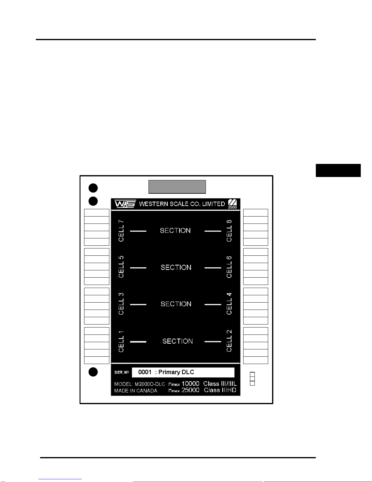
Figure 2: Remote DLC slave Corner & Section grouping
The following restrictions apply to allocating cells for hopper or sectional scales:
qHopper Scales
Hopper scale corners can be grouped on a single DLC, they cannot be spread across
two DLC terminal boxes. Hopper scales can be grouped from any of the cells on a
particular DLC slave terminal box.
qSectional Scales
A scale that uses sections will function in such a way that sections must be paired
together, across from each other as outlined in Figure 2. Two DLCs may be used for a
sectional scale allocation. Sections are allowed to span across DLC slaves. For
instance, the user might apply all 16 cells as a sectional scale which will provide 4
sections on the Primary DLC and 4 sections on the Secondary DLC, etc.
INTRODUCTION
+SIG
- SIG
SHLD
+EXC
- EXC
+SIG
- SIG
SHLD
+EXC
- EXC
+SIG
- SIG
SHLD
+EXC
- EXC
+SIG
- SIG
SHLD
+EXC
- EXC
- EXC
+EXC
SHLD
- SIG
+SIG
- EXC
+EXC
SHLD
- SIG
+SIG
- EXC
+EXC
SHLD
- SIG
+SIG
- EXC
+EXC
SHLD
- SIG
+SIG
STATUS
LINK
TX
DIGITAL LINK
ID
SELECT
PRM
SEC
Tabla de contenidos
Manuales populares de Panel táctil de otras marcas

IBASE Technology
IBASE Technology ASTUT-152-RE1S Manual de usuario

YASKAWA
YASKAWA TP 610C Manual de usuario

B&R
B&R Power Panel C Series Manual de usuario

Beijer Electronics
Beijer Electronics X2 control Manual de usuario

AXIOMTEK
AXIOMTEK GOT321W-521 Manual de usuario

TRIDONIC.ATCO
TRIDONIC.ATCO x-touchBOX Manual de usuario