Wespot SecNurse Manual de usuario

W
espot
SecNurse
EN
USER’S GUIDE
A NEW GENERATION TECHNICAL AIDS

This manual is published by OPTEX, without any warranty. Improvements and changes to this
manual necessitated by typographical errors, inaccuracies of current information, or improvements
to programs and/or equipment, may be made by OPTEX at any time and without notice. Such
changes will, however, be incorporated into new editions of this manual including those on our
web site www.wespot.com.
All rights reserved
© OPTEX Technologies B.V., 2009
version 4.4

1. Introduction 4
2. Equipment 5
Standard package content 5
Connectors/cables for connection to Nurse call systems 5
Standard order configurations 6
Accessories 6
Indication of parts 7
3. Installation 8
Mount the sensor on the wall 9
Connect the sensor 11
Specifications and connection diagram 12
Switching diagrams 13
Configure the detection zone 14
Adjust the sensor to the individual 16
Set the timer and sensitivity 16
Test 17
4. Using the sensor 19
Activate and deactivate the sensor 19
An alarm is sent 20
After an alarm has been sent 21
Second output contact 22
5. Consider the following 23
Situations resulting in an alarm 23
Intended target group 23
Prerequisites 23
Interfering factors 24
6. Maintenance 25
Clean the sensor 25
Test once a week 25
7. Troubleshooting 26
Self-learning error function 26
The sensor does not send an alarm 27
The sensor sends false alarms 28
Problems when configuring the bed zone 28
List of contents

- 4 -
- 5 -
The SecNurse is a bed occupancy detector for beds in nursing homes and elderly care envi-
ronments. An alarm is sent when the patient leaves the bed, or leaves the bed and does
not return within a specified time.
The sensor is based on vision technology. With this technology the sensor can see and
interpret situations. The greatest advantage with this technology is that the sensor, to a
high extent, can be adjusted to the patient’s needs. Other advantages are longer pro-
duct lifetime than comparable products and no need for hygienical maintenance, due to
the fact that the sensor does not demand physical contact.
Another advantage of the SecNurse is the adjustable sensitivity. The sensor can either send
an alarm when the patient leaves the bed or as soon as the patient sits on the bed edge.
In addition to this User´s Guide there is a shortguide with the most common functions.
Important!
The sensor is a technical aid, which substantially increases the efficiency per patient at regu-
lar supervision. However, it is only a complement to regular supervision, the SecNurse is not
intended to replace ordinary supervision of the patient by the nursing staff. During certain situ-
ations, the sensor might fail to detect that the patient leaves the bed, incorrect usage or incor-
rect mounting substantially increases the risk. All staff and other concerned should be clearly
informed about these matters. As a result of this Optex can therefore not be responsible for
direct or indirect injuries that arise in connection with or as a result of using the sensor.
1. Introduction

- 5 -
Standard package content
- 1 SecNurse
- 4 m. cable with RJ45 connector
- Mounting bracket (including 2 screws and 2 plugs)
- Remote control (including 2 x AAA-batteries)
- Manual and shortguide
Available connectors & cables for connection to Nurse call systems*
CModular Y adapter (3 x RJ45)
D2 Terminalblocks to RJ45 with 20 cm cable, COM-NO-NC type
E6,3 mm. mono Jack to RJ45 with 2 m cable, COM-NO type
F6,3 mm. stereo Jack to RJ45, with 2 m cable, COM-NO-NC type
GMini-DIN 8pol. to RJ45 with 2 m cable
HRJ45 to RJ45 extension cable with 2 m cable
IModular connector (2 x RJ45)
* Please specify on your order (see page 6)
2. Equipment

- 6 -
2. Equipment
- 7 -
Standard order configurations
SecNurse, including EU power supply unit, connectors & cables
SecNurse-EUCD EU power supply 12V DC with C + D
SecNurse-EUCE EU power supply 12V DC with C + E
SecNurse-EUCF EU power supply 12V DC with C + F
SecNurse-EUCG EU power supply 12V DC with C + G
SecNurse-EUCH EU power supply 12V DC with C + H
SecNurse, including UK power supply unit, connectors & cables
SecNurse-UKCD UK power supply 12V DC with C + D
SecNurse-UKCE UK power supply 12V DC with C + E
SecNurse-UKCF UK power supply 12V DC with C + F
SecNurse-UKCG UK power supply 12V DC with C + G
SecNurse-UKCH UK power supply 12V DC with C + H
SecNurse, including US power supply unit, connectors & cables
SecNurse-USCD US power supply 12V DC with C + D
SecNurse-USCE US power supply 12V DC with C + E
SecNurse-USCF US power supply 12V DC with C + F
SecNurse-USCG US power supply 12V DC with C + G
SecNurse-USCH US power supply 12V DC with C + H
SecNurse-HI SecNurse, without power supply, with H + I (extension cable)
SecNurse-Retrofit SecNurse including 4 m. cable with RJ45 connector
Accessories
SecNurse RC SecNurse universal Remote Control, T-33, universal type, incl. Batteries
SecNurse MB SecNurse wall Mounting Bracket for required detection angle
SecNurse PS Power Supply unit EU, UK or US
Software
Armed mode Optional software for the second output contact. The “out of bed
mode” will be delivered automatically for the second output contact.

- 7 -
2. Equipment
Indication of parts
ON/OFF button
The red button
activates and
deactivates the
sensor.
See chapter 4,
Using the sensor
Installation buttons
These buttons are
used during the
installation to con-
figure the bed zone.
See chapter 3,
Installation.
Timer and sensitivity
configuration buttons
These buttons are used
to adjust the timer and
sensitivity settings.
See chapter 3,
Installation.
room / foot wall / head
W
espo t
optics
IR-LEDs
night illuminationLEDs
user interface
SecNurse dimensions
(including mounting bracket):
166 x 68 x 77 (w x h x d)
Mounting
bracket
20 min
0 min
0 min
3 min
5 min
10 min

- 8 -
- 9 -
The installation procedure consists of five steps:
1. Mount the sensor on the wall
2. Connect the sensor
3. Configure the bed zone
4. Set timer and sensitivity settings
5. Make a functional test
Mounting instructions
In order to get the sensor to work in a satisfying way, it must be mounted correctly.
The first step in the mounting procedure is to attach the mounting bracket on the wall.
Thereafter the sensor can be easily snapped on the bracket. The design of the bracket
allows you to remove the sensor from the bracket, in order to move the sensor from one
bed to another.
The SecNurse can be mount on two different heights. When the bed zone has been con-
figured, the sensor will automatically recognize which mounting height is being used.
At both mounting positions it is important that the sensor is mounted horizontally, above
the middle of the bed and on the wall. This is important for a correct detection angle.
Large pieces of furniture should not be placed close to the bed, since this will affect the
detection performance negatively.
3. Installation
IMPORTANT!
The installation must be made in a correct way in
order to get proper functionality.
IMPORTANT!
Always use the mounting bracket for optimal
performance.

- 9 -
3. Installation
Mount the sensor on the wall
The sensor must be mounted either above the head end of the bed or above the long side
of the bed, according to the images below.
In both cases the sensor should be placed above the centre of the bed side.
Above the head end of the bed Above the long side of the bed
If it is possible to install the sensor in both ways, the long side mounting should be pre-
ferred if a lifting pole is mounted on the bed or if the detection sensitivity setting should
be set to detect the patient on the bed edge, see chapter 4, Using the sensor.
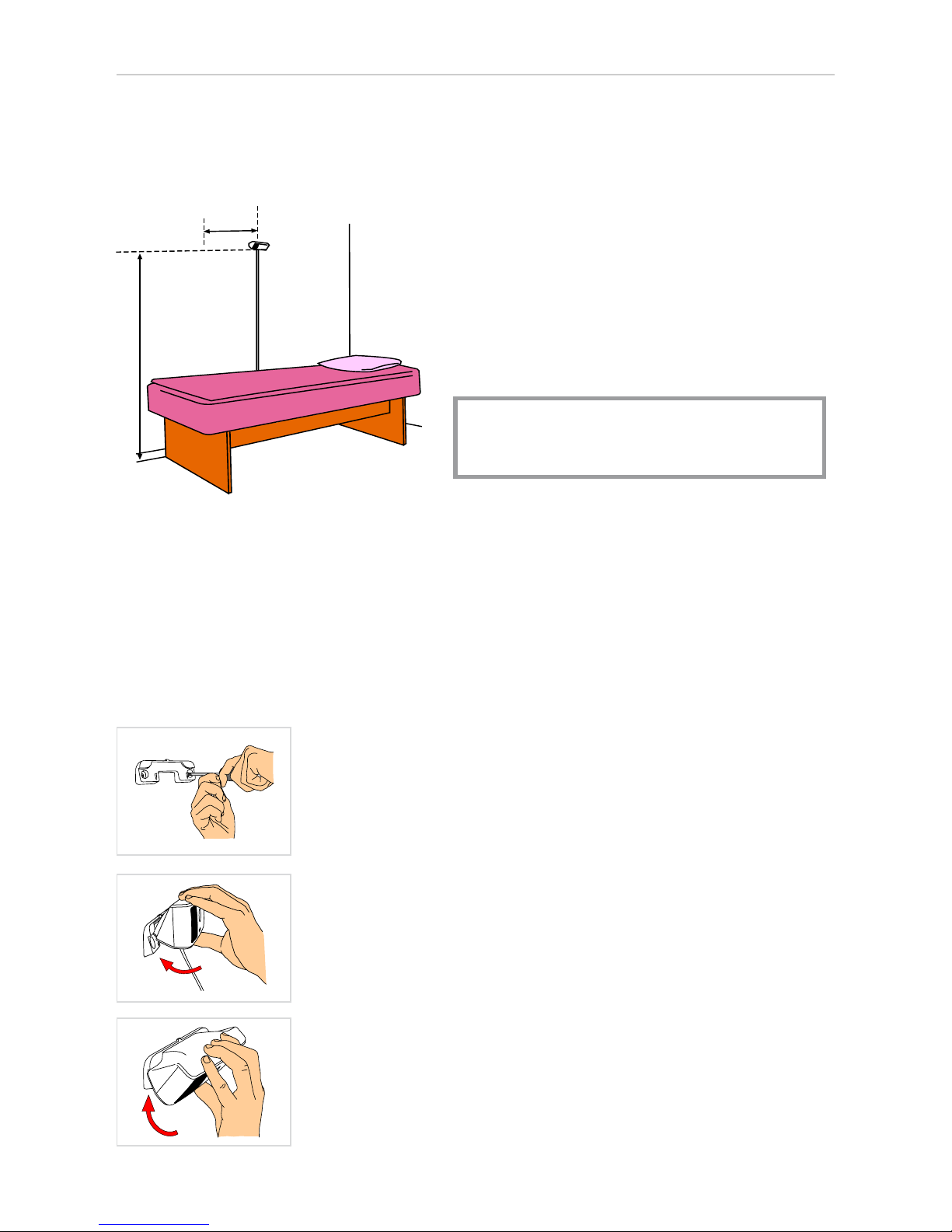
Mounting position 1. Above the head end of the bed
1a. If there is not a lifting pole mounted on the bed,
the sensor should be placed 180 cm above the floor,
distance A in the figure.
b. If there is a lifting pole mounted on the bed, the
sensor should be placed 200 cm above the floor and
the vertical distance between sensor and lifting pole
must be at least 40 cm, distance B in the figure.
Note! When the black mark on the sensor cord
reaches the floor, the mounting height is 200 cm
and when the red mark reaches the floor, the
mounting height is 180 cm.
2 Place the bed close to the wall with the sensor
placed just above the middle of the bed, according
to the figure to the left.
AB
- 10 -
3. Installation
- 11 -
Fasten the mounting bracket
Fasten the mounting bracket on the wall, thereafter the sensor can easily be snapped on
the bracket.
A
B
Mounting position 2. Above the long side of the bed
Fasten the mounting bracket on the wall.
It is very important that the mounting bracket is placed horizon-
tally.
Place the sensor in the two notches of the mounting
bracket.
Gently press the sensor downwards.
This procedure is reversible, which makes the sensor easy to
move to another bed.
1. Mount the sensor 180 cm above the
floor, distance A. Normally the sensor
should be placed above the middle of the
long side, but if a lifting pole is mounted
on the bed, the sensor should be 10-20
cm closer the foot end of the bed, dis-
tance B.
Note! When the red mark on the sensor
cord reaches the floor, the mounting
height is 180 cm.
2. Place the bed close to the wall with the
sensor placed just above the middle of
the bed, or 10-20 cm closer to the foot
end if there is a lifting pole on the bed.
Tabla de contenidos


