Wenglor P1MH Series Manual de usuario

Operating Instructions
EN
Translation of the original operating instructions
Subject to change without notice
Available as PDF file only
Version 1.0.0
As of: 10/19/2023
www.wenglor.com
P1MHxxx
Reex Sensors with Background Suppression
High-End with Teach-In

2
Table of Contents
1. General��������������������������������������������������������������������������������������������������������������������������������������4
1.1 Information Concerning these Instructions .............................................................................................4
1.2 Explanation of Symbols ..........................................................................................................................4
1.3 Limitation of Liability ...............................................................................................................................5
1.4 Copyrights...............................................................................................................................................5
2. For Your Safety ������������������������������������������������������������������������������������������������������������������������6
2.1 Use for Intended Purpose.......................................................................................................................6
2.2 Use for Other than the Intended Purpose...............................................................................................6
2.3 Personnel Qualifications .........................................................................................................................6
2.4 Modification of Products ........................................................................................................................7
2.5 General Safety Precautions....................................................................................................................7
2.6 Laser/LED Warnings...............................................................................................................................7
2.7 Approvals and Protection Class.............................................................................................................7
3. Technical Data�������������������������������������������������������������������������������������������������������������������������� 8
3.1 Technical Data........................................................................................................................................8
3.1.1 Light Spot Diameter .....................................................................................................................9
3.1.2 Switching Distance Deviation.....................................................................................................10
3.2 Complementary Products .....................................................................................................................11
3.3 Layout ...................................................................................................................................................11
3.4 Control Panel ........................................................................................................................................12
3.5 Scope of Delivery..................................................................................................................................12
4. Transport and Storage�����������������������������������������������������������������������������������������������������������13
4.1 Transport ..............................................................................................................................................13
4.2 Storage .................................................................................................................................................13
5. Installation and Electrical Connection���������������������������������������������������������������������������������13
5.1 Installation.............................................................................................................................................13
5.2 Electrical Connection ............................................................................................................................14
5.3 Diagnosis ..............................................................................................................................................15
6. Settings�����������������������������������������������������������������������������������������������������������������������������������16
7. Functions Overview���������������������������������������������������������������������������������������������������������������17
7.1 Teach-In Mode......................................................................................................................................17
7.1.1 Foreground Teach-In .................................................................................................................17
7.1.2 Background Teach-In.................................................................................................................17
7.2 Pin E/A2 Function .................................................................................................................................18
7.2.1 External Teach-In Input (Default Setting)...................................................................................18
7.2.2 Error Output ...............................................................................................................................18
7.3 Additional Functions and Settings ........................................................................................................19
8. IO-Link�������������������������������������������������������������������������������������������������������������������������������������19
9. NFC������������������������������������������������������������������������������������������������������������������������������������������19
10� Maintenance Instructions������������������������������������������������������������������������������������������������������20
11. Proper Disposal���������������������������������������������������������������������������������������������������������������������� 20
Table of Contents

3Reflex Sensors with Background Suppression
12. Appendix���������������������������������������������������������������������������������������������������������������������������������20
12.1 List of Abbreviations ...........................................................................................................................20
12.2 Change Index for the Operating Instructions ......................................................................................20
12.3 Declarations of Conformity .................................................................................................................20
4General
1� General
1�1 Information Concerning these Instructions
• These instructions apply to products designated P1MHxxx.
• These instructions make it possible to use the product safely and efficiently.
• These instructions are an integral part of the product and must be kept on hand for the entire duration of its
service life.
• Local accident prevention regulations and national work safety regulations must be complied with as well.
• The product is subject to further technical development, and thus the information contained in these operat-
ing instructions may also be subject to change. The current version can be found at
www.wenglor.com in the product’s separate download area.
NOTE!
The operating instructions must be read carefully before using the product and must be kept
on hand for later reference.
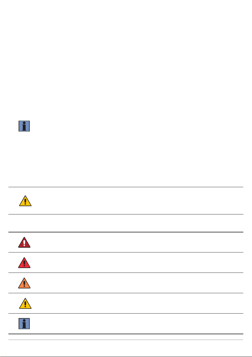
1�2 Explanation of Symbols
• Safety precautions and warnings are emphasized by means of symbols and signal words.
• Safe use of the product is only possible if these safety precautions and warnings are adhered to.
The safety precautions and warnings are laid out in accordance with the following principle:
SIGNAL WORD!
Type and source of danger!
Possible consequences in the event that the hazard is disregarded.
• Measures for averting the hazard.
The meanings of the signal words, as well as the scope of the associated hazards, are listed below:
DANGER!
This signal word indicates a hazard with a high degree of risk which, if not avoided, results in
death or severe injury.
WARNING!
This signal word indicates a hazard with a medium degree of risk which, if not avoided, may
result in death or severe injury.
CAUTION!
This signal word indicates a hazard with a low degree of risk which, if not avoided, may result
in minor or moderate injury.
ATTENTION!
This signal word draws attention to a potentially hazardous situation which, if not avoided,
may result in property damage.
NOTE!
A note draws attention to useful tips and suggestions, as well as information regarding effi-
cient, error-free use.

5Reflex Sensors with Background Suppression
1�3 Limitation of Liability
• The product has been developed in consideration of the current state-of-the-art technology, as well as
applicable standards and guidelines. Subject to change without notice.
• A valid declaration of conformity can be accessed at www.wenglor.com in the product’s separate download
area.
• wenglor sensoric elektronische Geräte GmbH (hereinafter referred to as “wenglor”) excludes all liability in
the event of:
• Non-compliance with the instructions,
• Use of the product for purposes other than those intended,
• Use by untrained personnel,
• Use of unapproved spare parts,
• Unapproved modification of products.
• These operating instructions do not include any guarantees from wenglor with regard to the described pro-
cedures or specific product characteristics.
• wenglor assumes no liability for printing errors or other inaccuracies contained in these operating instruc-
tions unless wenglor was verifiably aware of such errors at the point in time at which the operating instruc-
tions were prepared.
1�4 Copyrights
• The contents of these instructions are protected by copyright law.
• All rights are reserved by wenglor.
• Commercial reproduction or any other commercial use of the provided content and information, in particular
graphics and
images, is not permitted without previous written consent from wenglor.

6For Your Safety
2� For Your Safety
2�1 Use for Intended Purpose
This wenglor product is intended for use in accordance with the following functional principle:
Reflex Sensors with Background Suppression
Reflex sensors with background suppression evaluate the light reflected by objects. As they operate according
to the angle measurement principle, the object’s color, shape, and surface finish have practically no influence
on the detection range. Even dark objects are reliably recognized against bright backgrounds. When the object
reaches the selected detection range, the sensor’s output is switched.
This product can be used in the following industry sectors:
• Special-purpose mechanical
engineering
• Heavy mechanical engineering
• Logistics
• Automotive industry
• Food industry
• Packaging industry
• Pharmaceuticals industry
• Plastics industry
• Woodworking industry
• Consumer goods industry
• Paper industry
• Electronics industry
• Glass industry
• Steel industry
• Aviation industry
• Chemicals industry
• Alternative energies
• Raw materials extraction
2�2 Use for Other than the Intended Purpose
• Not a safety component in accordance with 2006/42/EC (Machinery Directive).
• The product is not suitable for use in potentially explosive atmospheres.
• The product may be used only with accessories supplied or approved by wenglor, or in combination with
approved products. A list of approved accessories and combination products can be found at www.wenglor.
com on the product detail page.
DANGER!
Risk of personal injury or property damage in case of use for other than the intended
purpose!
Use for other than the intended purpose may lead to hazardous situations.
• Instructions regarding use for intended purpose must be observed.
2�3 Personnel Qualifications
• Suitable technical training is a prerequisite.
• In-house electronics training is required.
• Trained personnel who use the product must have (uninterrupted) access to the operating instruc-
tions.

7Reflex Sensors with Background Suppression
DANGER!
Risk of personal injury or property damage in case of incorrect
initial start-up and maintenance!
Personal injury and damage to equipment may occur.
• Adequate training and qualification of personnel.
2�4 Modification of Products
DANGER!
Risk of personal injury or property damage if the product is modified!
Personal injury and damage to equipment may occur. Noncompliance may result in
loss of the CE mark and voiding of the warranty.
• Modification of the product is impermissible.
2�5 General Safety Precautions
NOTE!
• These instructions are an integral part of the product and must be kept on hand for the
entire duration of its service life.
• In the event of possible changes, the respectively current version of the operating instruc-
tions can be accessed at www.wenglor.com in the product’s separate download area.
• Read the operating instructions carefully before using the product.
• The sensor must be protected against contamination and mechanical influences.
2�6 Laser/LED Warnings
The respective laser class or LED risk group is listed in the product’s technical data.
LASER CLASS 1
EN 60825-1:2014
Laser Class1 (EN60825-1)
Applicable standards and safety regulations must be observed.
2�7 Approvals and Protection Class

8Technical Data
3� Technical Data
3�1 Technical Data
Optical Data
Service life (ambient temp. = 25 °C) 100,000 h
Max. permitted ambient light 10,000 lux
Electrical Data
IO-Link supply voltage 18…30 V DC
Switching output voltage drop < 2 V
Switching output switching current 100 mA
Switching output residual current < 50 µA
Short-circuit proof Yes
Reverse polarity protected Yes
Overload-proof Yes
Lockable Yes
Interface IO-Link
IO-Link version 1.1
Protection class III
Mechanical Data
Housing material Plastic
Degree of protection IP67/IP68
Optic cover PMMA

9Reflex Sensors with Background Suppression
Order No.
Technical Data
P1MH
102 104 203 206
Principle Electronic background suppression
Detection range 200 mm
Setting range 40...200 mm 30...200 mm
Switching hysteresis < 5% < 10%
Light source Red light Laser (red)
Laser class (EN 60825-1) — 1
Risk group (EN 62471) 0 —
Light spot diameter See table 1 See table 2
Supply voltage 15...30 V DC
Current consumption (operating voltage = 24 V) < 20 mA
Temperature range −40…60°C −25...60°C
Temperature drift < 5%
Switching frequency 1,000 Hz 1,600 Hz
Response time 0.5 ms 0.31 ms
Switching frequency (2 switching outputs) 100 Hz
Response time (2 switching outputs) 5 ms
Setting method Teach-in/NFC
Output function PNP NO × ×
NPN NO × ×
Connection type Plug: M12x1, 4-pin
Connection diagram no. 865
Suitable connection equipment no. 360
3�1�1 Light Spot Diameter
Range 40 mm 100 mm 200 mm
Light spot diameter 9 mm 8 mm 7 mm
Table 1
Range 30 mm 100 mm 200 mm
Light spot diameter 2 mm 1.5 mm 1.5 mm
Table 2

10 Technical Data
3�1�2 Switching Distance Deviation
Typical characteristic curve based on white (90% remission)
P1MH102, P1MH104: P1MH203, P1MH206:
Sr = switching distance
dSr = change in switching distance
Black, 6% remission
Gray, 18% remission
Otros manuales para P1MH Series
1
Este manual sirve para los siguientes modelos
4
Tabla de contenidos
Otros manuales de Sensor de seguridad de Wenglor

Wenglor
Wenglor IR2D002 Manual de usuario

Wenglor
Wenglor PNBC Series Manual de usuario

Wenglor
Wenglor SS2-00VA000R2 Manual de usuario

Wenglor
Wenglor Y1TA Series Manual de usuario

Wenglor
Wenglor IR2D001 Manual de usuario

Wenglor
Wenglor P1KK008 Manual de usuario

Wenglor
Wenglor OPT2139 Manual de usuario

Wenglor
Wenglor P1PY1 Series Manual de usuario

Wenglor
Wenglor IR 00 Series Manual de usuario

Wenglor
Wenglor B60 Series Manual de usuario


